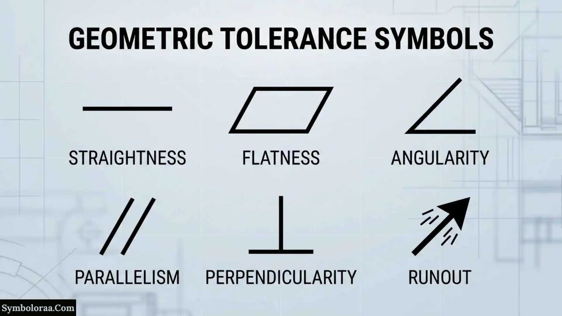
Geometric tolerance symbols are the visual language used in Geometric Dimensioning and Tolerancing (GD&T) to communicate how much a manufactured part is allowed to vary from its intended geometry. If you are trying to read an engineering drawing, understand a GD&T chart, choose the right tolerance for a feature, or learn what symbols such as position, flatness, perpendicularity, and runout mean, this guide explains the subject from the ground up.
A geometric tolerance symbol is only one part of a complete requirement. The tolerance value, feature control frame, datum references, modifiers, feature type, and governing standard can all affect how a requirement is interpreted.
ASME Y14.5 establishes symbols, definitions, rules, requirements, defaults, and recommended practices for stating and interpreting GD&T on engineering drawings, digital data files, and related documents. ISO 1101:2017 provides the symbol language and interpretation rules for geometrical specifications covering form, orientation, location, and run-out. ISO currently lists the 2017 edition as confirmed and current.
This guide covers the major geometric tolerance symbols, what each control does, when it is useful, common mistakes, real manufacturing examples, feature control frames, datums, inspection, ASME versus ISO terminology, and a practical decision guide for selecting the right control.
Quick Answer: What Are Geometric Tolerance Symbols?
Geometric tolerance symbols are standardized symbols that specify allowable variation in the form, orientation, location, profile, or runout of a part feature.
They are used in engineering drawings and digital product definitions to communicate requirements that ordinary plus/minus dimensions cannot always express clearly.
The major GD&T controls include:
| Control group | Geometric characteristics | Main purpose |
| Form | Straightness, flatness, circularity, cylindricity | Controls shape |
| Profile | Profile of a line, profile of a surface | Controls contours and surfaces |
| Orientation | Angularity, perpendicularity, parallelism | Controls angular relationships |
| Location | Position, concentricity, symmetry | Controls feature relationships and location |
| Runout | Circular runout, total runout | Controls variation during rotation |
The key idea is simple:
Dimensions tell you how big or how far. Geometric tolerances tell you how accurately the geometry must behave.
For professional work, however, the exact interpretation must follow the applicable standard and drawing requirements.
Why Geometric Tolerances Matter in Engineering and Manufacturing
A component can have dimensions that fall within their specified limits and still fail to assemble or function correctly.
Imagine a mounting plate with four holes. The diameter of every hole may be acceptable, but if one hole is located too far from its intended position, the mating component may not fit.
Likewise, a shaft can have an acceptable diameter while still having unacceptable straightness, orientation, or runout.
GD&T solves these problems by allowing the designer to communicate functional relationships, rather than relying only on individual size dimensions.
How GD&T improves design communication
A good geometric tolerance requirement can help different teams understand the same design intent:
- Designers define functional requirements.
- Manufacturers understand allowable variation.
- Machinists know what geometry must be controlled.
- Inspectors know what characteristics must be evaluated.
- Quality teams can compare measured results with defined requirements.
- Assembly teams receive more predictable components.
ASME describes GD&T as an essential tool for communicating design intent, fit, function, and interchangeability. It also notes that uniform specification and interpretation can reduce manufacturing guesswork.
Why ordinary dimensions are sometimes not enough
Suppose a drawing specifies a shaft as 20.00 ± 0.05 mm.
That controls its size range.
It does not, by itself, answer every possible question about:
- Straightness
- Roundness
- Axis orientation
- Surface profile
- Runout
- Relationship to another feature
Those requirements may need separate geometric controls.
The Five Main Categories of Geometric Tolerance
Learning GD&T becomes much easier when the symbols are grouped by purpose.
The five major categories are:
- Form
- Profile
- Orientation
- Location
- Runout
Each category answers a different engineering question.
Form: Is the feature shaped correctly?
Form controls focus on the shape of an individual feature.
They include:
- Straightness
- Flatness
- Circularity
- Cylindricity
A form tolerance generally does not establish the feature’s relationship to a datum.
Profile: Does the feature follow the intended contour?
Profile controls regulate the shape of a line or surface.
They include:
- Profile of a line
- Profile of a surface
Profile is especially useful for complex curved or irregular geometry.
Orientation: Is the feature pointing in the correct direction?
Orientation controls define relationships such as:
- Parallel
- Perpendicular
- At a specified angle
The major controls are:
- Parallelism
- Perpendicularity
- Angularity
Location: Is the feature in the correct place?
Location controls address where a feature is located relative to a reference framework.
The major controls traditionally grouped here include:
- Position
- Concentricity
- Symmetry
Position is especially important for hole patterns and other features of size.
Runout: How much does the feature vary during rotation?
Runout controls are commonly used on rotating parts.
They include:
- Circular runout
- Total runout
These controls are important for shafts, bearing surfaces, wheels, rotors, and other precision rotating components.
Also Check This Post: 79+ Symbols in Spanish: What Do These Common Signs Mean?
Form Geometric Tolerance Symbols Explained
Form tolerances control the shape of a feature without primarily defining its relationship to another feature.
Straightness
Straightness controls how much a line element or applicable derived feature may deviate from perfect straightness.
Consider a long shaft.
Its diameter might be within size limits, but the shaft could still bow slightly. If that bow affects assembly or movement, a straightness requirement may be needed.
Real-world example:
A precision guide shaft needs to remain sufficiently straight so a sliding component can move smoothly along it.
Common mistake:
Assuming that a tight diameter tolerance automatically guarantees a perfectly straight shaft.
It does not.
Flatness
Flatness controls how much a surface may deviate from a theoretically perfect plane.
A flatness tolerance creates a controlled zone between two parallel planes.
Example:
A machine mounting surface may need to be sufficiently flat to provide stable contact with another component.
Flatness is about the surface itself. It does not automatically establish parallelism with another surface.
Important distinction:
- Flatness → controls surface form.
- Parallelism → controls orientation relative to a datum.
Circularity
Circularity controls the roundness of individual circular elements.
A circular feature can have an acceptable average or size-related dimension while still having an imperfect circular shape.
Example:
A precision bearing surface may require controlled circularity so the component operates properly.
Circularity is a form control. It does not establish where the feature is located.
Cylindricity
Cylindricity controls the overall cylindrical form of a surface.
It is broader than circularity because it addresses the cylindrical surface as a whole.
Example:
A precision shaft may need its cylindrical surface controlled so that its overall form remains within the specified tolerance zone.
A useful learning shortcut is:
Circularity = individual circular sections
Cylindricity = overall cylindrical surface
Profile Geometric Tolerance Symbols Explained
Profile controls are valuable when the intended geometry is not simply a flat plane, straight line, or perfect cylinder.
Profile of a line
Profile of a line controls the shape of a two-dimensional line element.
It can be useful for:
- Curved cross-sections
- Contoured surfaces
- Molded profiles
- Machined curves
- Sections of complex geometry
Example:
An automotive component may contain a specific curved section that must remain close to the theoretically exact profile.
Instead of controlling many individual points, a profile requirement can communicate the intended contour more directly.
Profile of a surface
Profile of a surface controls the three-dimensional shape of a surface.
It is particularly useful for:
- Castings
- Molded components
- Aerodynamic parts
- Automotive body panels
- Complex housings
- Freeform machined surfaces
- Turbine or fluid-flow components
Profile can become especially powerful when a design needs to control a complex surface relative to a datum reference framework.
ASME’s Y14.5 material specifically includes profile tolerances as a major part of the GD&T system.
Orientation Geometric Tolerance Symbols Explained
Orientation controls define how a feature is oriented relative to a reference.
Parallelism
Parallelism controls whether a feature maintains the required parallel relationship to a datum.
Example:
A machined rail surface may need to remain parallel to a reference surface so that a moving assembly operates correctly.
Parallelism does not simply mean “the two surfaces must be the same distance apart.” The exact interpretation depends on the feature and specification.
Perpendicularity
Perpendicularity controls a 90-degree relationship.
For example, a hole axis may need to remain perpendicular to a mounting surface.
Real manufacturing scenario:
Suppose a bearing housing contains a bore that must be perpendicular to a mounting face. A dimensional diameter requirement alone does not adequately describe that angular relationship.
Perpendicularity can address the functional requirement.
Angularity
Angularity controls orientation at a specified basic angle.
It differs from:
- Parallelism, which establishes a parallel relationship.
- Perpendicularity, which establishes a 90-degree relationship.
- Angularity, which can establish another specified angle.
Example:
A machined bracket contains a surface designed at 30° to a datum plane. Angularity may be appropriate when that angular relationship is the characteristic that matters.
Location Geometric Tolerance Symbols Explained
Location controls address the relationship and placement of features.
Position
Position is one of the most important GD&T controls, especially for holes and patterns.
It controls the location of a feature relative to its theoretically exact location and applicable datum reference framework.
Example:
Imagine a plate with four mounting holes.
Instead of independently tolerancing horizontal and vertical distances for every hole, a position requirement can define how far the actual feature may deviate from its intended location.
This can communicate design intent more directly.
ASME’s Y14.5 material includes feature-of-size concepts, datum reference frameworks, composite position tolerances, and related modifiers.
Concentricity
Concentricity controls the relationship between applicable derived median points and a datum axis.
This is a specialized control and should not be confused with the simple visual idea of “two circles sharing the same center.”
In functional design, another control may sometimes communicate the actual requirement more directly.
Practical lesson:
Do not select concentricity simply because two cylindrical features appear as though they should be centered. First identify the actual functional requirement.
Symmetry
Symmetry controls the relationship of applicable derived median points to a datum plane.
Like concentricity, it is a specialized control that requires careful interpretation.
The important engineering question is not:
“Which GD&T symbol looks closest to my drawing?”
It is:
“What physical relationship must the part maintain for the assembly to work?”
That question usually leads to a better tolerance choice.
Runout Geometric Tolerance Symbols Explained
Runout controls are especially important for components that rotate.
Circular runout
Circular runout controls variation at individual circular sections as a feature rotates around a datum axis.
A simple way to visualize it is to imagine a dial indicator touching a rotating shaft.
If the indicator moves as the shaft rotates, the measured movement can reveal rotational variation.
Circular runout is concerned with individual cross-sections rather than the entire surface simultaneously.
Total runout
Total runout controls variation across an entire surface as the part rotates about a datum axis.
It therefore provides broader control than circular runout.
Example:
A precision rotating shaft may need its complete bearing surface to remain controlled during rotation. Total runout can address the overall surface behavior.
Circular runout vs. total runout
| Characteristic | Circular Runout | Total Runout |
| Evaluation | Individual circular sections | Entire controlled surface |
| Typical application | Local rotational variation | Overall surface variation |
| Scope | More localized | More comprehensive |
| Common parts | Shafts, bores, rotating surfaces | Precision rotating surfaces |
The exact inspection procedure should follow the applicable drawing and standard.
How to Read a Feature Control Frame
The feature control frame is the rectangular structure used to communicate a geometric tolerance requirement.
A simplified conceptual example is:
[Geometric Symbol] [Tolerance] [Datum Reference]
A real requirement may contain additional modifiers and references.
First identify the geometric characteristic
Start at the first compartment.
Ask:
What geometric property is being controlled?
For example:
- Form
- Orientation
- Location
- Profile
- Runout
Then identify the tolerance value
The tolerance value defines the permitted geometric variation.
Look carefully for symbols or modifiers that affect how the tolerance is applied.
Check the datum references
If the feature control frame references A, B, or C, locate those datum features on the drawing.
Do not interpret the geometric requirement in isolation.
Check the controlled feature
Follow the leader from the feature control frame to determine exactly what feature the requirement applies to.
This matters because the same geometric characteristic can have different implications depending on whether it controls a surface, feature of size, axis, or another applicable feature.
Understanding Datums and Datum Reference Frames
Datums are fundamental to understanding many GD&T requirements.
A datum provides a theoretically exact reference from which other geometric relationships can be established.
Primary, secondary, and tertiary references
A datum reference framework can use multiple datums to establish the required reference system.
A simplified example is:
Primary datum → Secondary datum → Tertiary datum
These references progressively establish the orientation and location needed to evaluate the part.
Why datum selection matters
Imagine a rectangular component with a mounting surface, side wall, and end wall.
The designer might need:
- The mounting surface to establish the primary reference.
- The side wall to establish another directional relationship.
- The end wall to complete the location framework.
Choosing datums based on actual assembly function is generally more meaningful than choosing convenient surfaces simply because they are easy to dimension.
Geometric Tolerance Symbols vs. Traditional Plus/Minus Tolerances
Traditional dimensional tolerancing remains useful, but it does not communicate every geometric requirement efficiently.
| Traditional dimensional tolerancing | GD&T |
| Mainly communicates size and dimensional limits | Communicates geometric requirements |
| Often uses ± dimensions | Uses standardized geometric controls |
| Can require many coordinate dimensions | Can express feature relationships directly |
| May not clearly communicate functional geometry | Designed to communicate design intent |
| Useful for straightforward dimensions | Particularly powerful for complex relationships |
For example, a hole diameter dimension tells you the acceptable hole size.
A position requirement can address where the hole is allowed to be relative to its theoretically exact location and datum reference framework.
These systems are often used together rather than treated as alternatives.
A Practical Decision Tree for Choosing a Geometric Tolerance
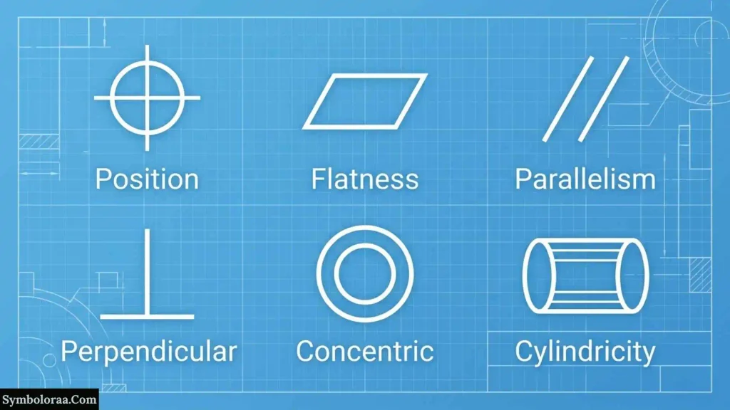
When deciding which geometric tolerance to use, start with the engineering problem.
What must be controlled?
↓
Is it the shape of a feature?
→ Consider straightness, flatness, circularity, or cylindricity.
↓
Is it a complex contour?
→ Consider profile of a line or profile of a surface.
↓
Is the feature’s orientation important?
→ Consider parallelism, perpendicularity, or angularity.
↓
Is feature location important?
→ Consider position or another applicable location control.
↓
Does the feature rotate around a datum axis?
→ Consider circular runout or total runout.
↓
Does the requirement involve a specialized relationship?
→ Review whether a control such as concentricity or symmetry is actually necessary.
The final choice should be based on function, manufacturability, inspection, and the applicable standard.
Real-World Examples of GD&T Applications
The best way to understand geometric tolerancing is to connect each control to a physical problem.
Example: Hole pattern on a mounting plate
A machine plate contains several holes used to attach another component.
The holes have acceptable diameters, but their locations are critical.
Primary concern: Location.
Likely control: Position.
Example: Machine mounting surface
A component must sit firmly against another surface.
The surface itself needs to remain sufficiently planar.
Primary concern: Form.
Possible control: Flatness.
Example: Shaft used with bearings
A shaft rotates inside bearings.
Its diameter, axis behavior, and rotational variation can affect performance.
Possible concerns:
- Cylindricity
- Straightness
- Runout
- Position or orientation, depending on the design
The correct control depends on the actual functional requirement.
Example: Angled bracket
A bracket has a machined face intended to sit at a defined angle to another reference.
Primary concern: Orientation.
Possible control: Angularity.
Example: Complex molded housing
A plastic housing contains curved surfaces that must fit another component.
Primary concern: Surface profile.
Possible control: Profile of a surface.
These examples show why selecting a symbol should begin with the function of the component, not with memorizing a symbol chart.
Common Mistakes When Using Geometric Tolerance Symbols
Even experienced teams can run into problems when tolerancing is treated as a symbol-selection exercise.
Mistake 1: Choosing a symbol before identifying the functional problem
A designer may start by asking:
“Which symbol should I use?”
A better question is:
“What failure am I trying to prevent?”
For example:
- Mislocated hole → location requirement.
- Uneven mounting surface → form requirement.
- Incorrect shaft rotation → runout-related requirement.
- Wrong angular relationship → orientation requirement.
Mistake 2: Confusing size with geometry
A size tolerance does not automatically control every geometric characteristic.
A shaft can be within diameter limits and still have geometric variation that matters to the assembly.
Mistake 3: Ignoring datums
A location or orientation requirement often cannot be properly understood without its datum reference framework.
Always identify the datum features before interpreting the requirement.
Mistake 4: Using unnecessarily tight tolerances
A smaller tolerance is not automatically a better tolerance.
An unnecessarily tight requirement can:
- Increase machining difficulty.
- Increase inspection demands.
- Increase production cost.
- Increase scrap risk.
- Require specialized equipment.
The goal is functional control, not maximum precision for its own sake.
Mistake 5: Treating ASME and ISO rules as identical
ASME Y14.5 and ISO 1101 are related but distinct standards frameworks.
ISO 1101 defines the symbol language and interpretation rules for geometrical specifications. ASME Y14.5 establishes its own GD&T rules, definitions, requirements, defaults, and recommended practices.
A drawing should clearly identify the governing standard.
Best Practices for Using GD&T
Good geometric tolerancing starts with function.
Start with assembly requirements
Ask what the component must do after manufacturing.
Does it need to:
- Mate with another part?
- Rotate?
- Seal?
- Slide?
- Locate?
- Support a load?
- Maintain a precise gap?
- Maintain a particular surface shape?
The answer helps identify which geometric relationships matter.
Use the least restrictive control that satisfies the function
Do not specify extreme precision unless the product actually requires it.
A functional tolerance that can be manufactured and inspected reliably is usually more useful than an unnecessarily restrictive one.
Select datums based on function
Datum features should reflect how the part is:
- Located
- Assembled
- Manufactured
- Inspected
Think about inspection during design
Before approving a tolerance, consider how it will be measured.
Potential inspection methods include:
- Coordinate measuring machines
- Dial indicators
- Surface plates
- Height gauges
- Optical measurement systems
- Functional gauges
- Specialized fixtures
The measurement method should be suitable for the specified requirement.
Geometric Tolerancing in CAD and Digital Product Definition
GD&T is no longer limited to traditional paper drawings.
Modern engineering workflows may communicate product requirements through:
- 2D drawings
- 3D CAD models
- Model-based definition
- Digital inspection systems
- Manufacturing software
- Coordinate measurement systems
ASME Y14.5 addresses GD&T use on engineering drawings and models defined in digital data files.
ISO 1101 also allows geometrical specifications to be associated with 3D CAD models through related digital product-definition practices.
This shift makes it increasingly important for engineers and manufacturers to understand not just the symbols but the underlying specification rules.
Also Check This Post: 67+ Symbols of Jesus: Powerful Christian Symbols Explained
ASME Y14.5 vs. ISO 1101: What Is the Difference?
This is an important issue for anyone working with international suppliers or engineering drawings.
| Area | ASME Y14.5 | ISO 1101 |
| System | GD&T | GPS |
| Purpose | Dimensioning and tolerancing | Geometrical product specification |
| Symbols | Yes | Yes |
| Form | Covered | Covered |
| Orientation | Covered | Covered |
| Location | Covered | Covered |
| Runout | Covered | Covered |
| Digital product definition | Addressed within the Y14 framework | Supported through related ISO GPS practices |
| Typical environment | Common in U.S.-based engineering | Widely used internationally |
ASME currently lists Y14.5-2018 (R2024) as its current Y14.5 standard information and describes it as the authoritative guideline for the GD&T design language.
ISO lists ISO 1101:2017 as the current confirmed edition and states that it defines the symbol language and interpretation rules for geometrical specifications.
The practical lesson is simple:
Always identify the governing standard before interpreting a technically important tolerance.
Do not assume that a symbol’s appearance means every rule surrounding it is identical under ASME and ISO.
How Geometric Tolerances Affect Manufacturing Cost
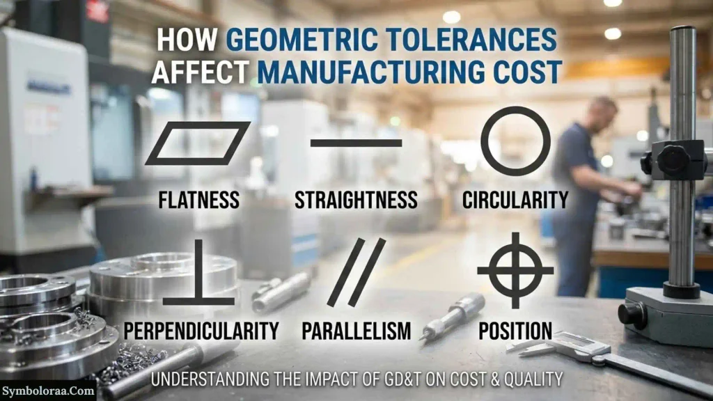
Tolerance selection has a direct relationship with manufacturing difficulty.
A requirement that is unnecessarily restrictive may require:
- More precise machines.
- Additional machining operations.
- More inspection time.
- Specialized fixtures.
- More frequent process adjustments.
- More expensive measurement equipment.
On the other hand, a tolerance that is too loose may allow parts that fail during assembly or operation.
The goal is therefore not:
“Make the tolerance as small as possible.”
The better goal is:
“Specify enough control to protect the functional requirement.”
This is one of the most important principles for practical tolerance design.
How to Build a GD&T Learning Path
If you are new to geometric tolerancing, trying to memorize every symbol at once can be confusing.
A better sequence is:
Stage 1: Learn basic terminology
Understand:
- Feature
- Feature of size
- Datum
- Tolerance zone
- Basic dimension
- Feature control frame
Stage 2: Learn form controls
Start with:
- Straightness
- Flatness
- Circularity
- Cylindricity
Stage 3: Learn orientation
Then study:
- Parallelism
- Perpendicularity
- Angularity
Stage 4: Learn location
Focus heavily on:
- Position
- Datum reference frameworks
- Feature patterns
Stage 5: Learn profile and runout
Move to:
- Profile of a line
- Profile of a surface
- Circular runout
- Total runout
Stage 6: Study modifiers and advanced applications
Finally learn the rules and modifiers relevant to your governing standard.
ASME’s own Y14.5 learning structure follows a progression that includes terminology and symbols, datum reference frames, form, orientation, position, profile, and runout.
Frequently Asked Questions About Geometric Tolerance Symbols
What are the main geometric tolerance symbols?
The major geometric characteristics include straightness, flatness, circularity, cylindricity, profile of a line, profile of a surface, angularity, perpendicularity, parallelism, position, concentricity, symmetry, circular runout, and total runout.
What is the most important GD&T symbol to learn first?
For beginners, it is useful to learn the form controls first because they establish the basic idea of geometric variation. Position is also particularly important because it is widely used for controlling feature location.
What does the position symbol mean?
Position controls the location of an applicable feature relative to its theoretically exact location and the applicable datum reference framework. Its complete interpretation depends on the tolerance value, modifiers, feature, and governing standard.
Is flatness the same as parallelism?
No. Flatness controls the form of a surface by itself. Parallelism controls orientation relative to a datum.
Is perpendicularity the same as angularity?
No. Perpendicularity controls a 90-degree relationship. Angularity controls orientation at a specified basic angle.
What is the difference between circularity and cylindricity?
Circularity controls the form of individual circular elements. Cylindricity controls the overall cylindrical form of a surface.
What is the difference between circular runout and total runout?
Circular runout evaluates rotational variation at individual circular sections. Total runout evaluates variation across the entire controlled surface during rotation.
Are GD&T symbols universal?
The symbols are standardized, but the complete rules and interpretation can depend on the governing standard. ASME Y14.5 and ISO 1101 should not automatically be treated as interchangeable systems.
Can GD&T be used in 3D CAD?
Yes. Modern product-definition workflows can communicate geometric specifications through digital models. Both ASME and ISO have standards frameworks addressing digital product definition.
Do geometric tolerances replace dimensional tolerances?
No. Dimensional and geometric tolerances serve different purposes and are commonly used together.
Why are datums important?
Datums establish the reference framework used to evaluate relationships between features. Many orientation and location requirements depend on properly defined datum references.
Should every part use GD&T?
Not every dimension requires a geometric tolerance. GD&T is most valuable where geometric relationships affect function, interchangeability, manufacturing, or inspection.
Can tighter tolerances improve product quality?
Not automatically. A tighter tolerance can improve control where the function requires it, but an unnecessarily tight tolerance can increase manufacturing and inspection costs without providing useful functional benefit.
Key Takeaways
The most important lessons about geometric tolerance symbols are:
- GD&T communicates geometric requirements that ordinary dimensions may not fully describe.
- Form controls include straightness, flatness, circularity, and cylindricity.
- Profile controls include profile of a line and profile of a surface.
- Orientation controls include parallelism, perpendicularity, and angularity.
- Position is a major tool for controlling feature location.
- Circular and total runout are important for rotating components.
- A symbol should never be interpreted without considering its complete feature control frame and drawing context.
- Datums establish the reference framework for many geometric requirements.
- Size tolerance and geometric tolerance are not the same thing.
- Tighter tolerances are not automatically better.
- Good GD&T begins with the functional requirement.
- Manufacturing and inspection capability should be considered before assigning a tolerance.
- ASME Y14.5 and ISO 1101 are separate standards frameworks.
- Always use the governing standard identified by the drawing, contract, organization, or project.
Conclusion
Geometric tolerance symbols are much more than marks placed on an engineering drawing. They form a structured language for communicating how a component’s geometry is allowed to vary while still meeting its intended function.
The most effective way to understand GD&T is to stop thinking of the symbols as isolated definitions. Instead, connect each symbol to the physical problem it solves.
If the problem is the shape of a feature, consider form controls. If the issue is a complex contour, profile may be appropriate. If the concern is orientation, look at parallelism, perpendicularity, or angularity. If a feature must be located accurately, position is often central to the requirement. If a component rotates, runout may become critical.
Just as important, learn to read the complete specification. The geometric characteristic, tolerance value, modifiers, datum references, controlled feature, and governing standard work together.
ASME Y14.5 and ISO 1101 provide authoritative frameworks for geometrical tolerancing, but they should not be assumed to have identical rules in every situation. ASME currently identifies Y14.5-2018 (R2024) as its current Y14.5 information, while ISO identifies ISO 1101:2017 as the current confirmed edition.
For professional design, manufacturing, inspection, or contractual decisions, use the applicable official standard and the specific requirements of the engineering documentation.
Also Check This Post: 87+ Dental Charting Symbols: A Quick Guide for Dental Students

I’m Jackson Miller, an American author inspired by mystery, adventure, and the unpredictable nature of life. I enjoy writing fast-moving stories filled with memorable characters, unexpected choices, and meaningful moments. Through my books, I want readers to experience new worlds while discovering something about courage, determination, and themselves.
Three Books:
The Edge of Tomorrow
Under a Broken Sky
The Road We Chose
 Madison Reed