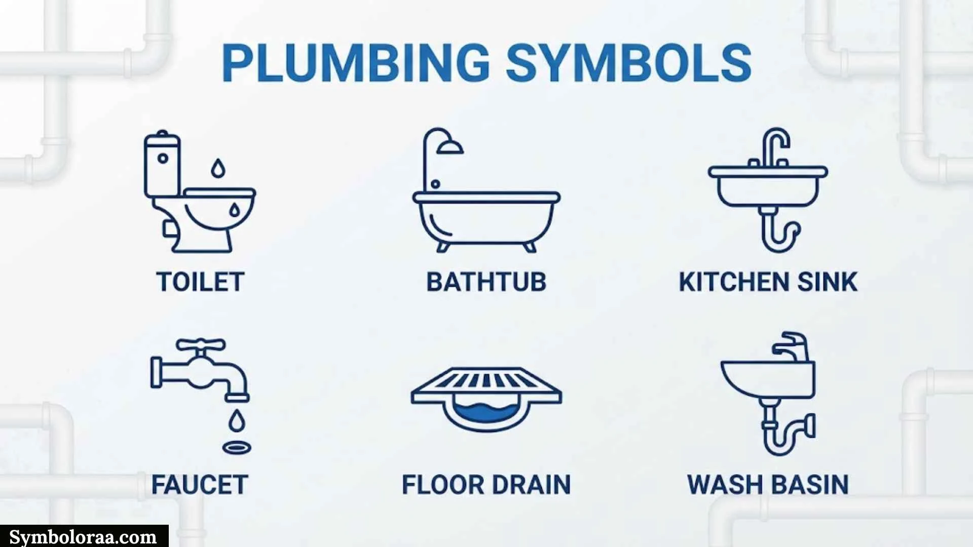
Plumbing symbols are the visual language used to represent pipes, fixtures, valves, drains, vents, connections, and equipment on technical drawings. Instead of drawing every plumbing component exactly as it looks in real life, designers use simple symbols and abbreviations to keep plans clear and easy to read.
This guide covers plumbing symbols and meanings, plumbing symbols with pictures, valve symbols, legends, charts, blueprints, architectural drawings, isometric diagrams, and residential plumbing plans. You will also find commonly used abbreviations such as CW, HW, HWR, V, FD, CO, and POC, along with practical examples for reading drawings.
One important point is that plumbing symbols are not completely identical on every project. ASPE publishes standardized plumbing drawing symbols and abbreviations, but its handbook also notes that government agencies, industry groups, and clients may require project-specific symbol lists. Always check the legend provided with the drawing before making a final interpretation.
Plumbing Symbols And Meanings
Plumbing symbols identify the components and services shown on a plumbing drawing. They can represent water-supply pipes, sanitary drainage, storm drainage, vents, valves, fixtures, cleanouts, risers, connections, and other equipment.
Some of the most useful plumbing abbreviations include:
| Symbol / Abbreviation | Meaning | Typical Use |
| CW | Cold Water | Cold-water supply |
| HW | Hot Water | Hot-water supply |
| HWR | Hot Water Return | Hot-water recirculation |
| TW | Tempered Water | Temperature-controlled water |
| V | Vent | Plumbing vent system |
| SS | Soil, Waste, Or Sanitary Sewer | Sanitary drainage |
| SD | Storm Drain / Rainwater Drain | Stormwater drainage |
| FD | Floor Drain | Drain at floor level |
| CO | Cleanout | Access to drainage piping |
| FCO | Floor Cleanout | Cleanout installed in a floor |
| WCO | Wall Cleanout | Cleanout located in a wall |
| HB | Hose Bibb | Water outlet for a hose |
| POC | Point Of Connection | Connection to another system |
| PRV | Pressure-Reducing Valve | Reduces downstream pressure |
| CV | Check Valve | Helps prevent reverse flow |
| GV | Gate Valve | Pipe isolation |
| BV | Ball Valve | Quick shutoff |
| TMV | Thermostatic Mixing Valve | Controls mixed-water temperature |
ASPE’s published plumbing symbol references include systems such as storm drains, sanitary systems, vents, cold water, hot water, hot-water return, tempered water, valves, cleanouts, floor drains, and points of connection.
The meaning of a symbol becomes clearer when you consider its line type, abbreviation, location, nearby notes, and connection to other components. A symbol should rarely be interpreted in isolation.
For example, FD near a bathroom floor may indicate a floor drain, while CO beside a drainage line commonly indicates a cleanout. A line marked CW normally identifies cold-water piping, while HW identifies hot-water piping.
Plumbing Symbols With Pictures
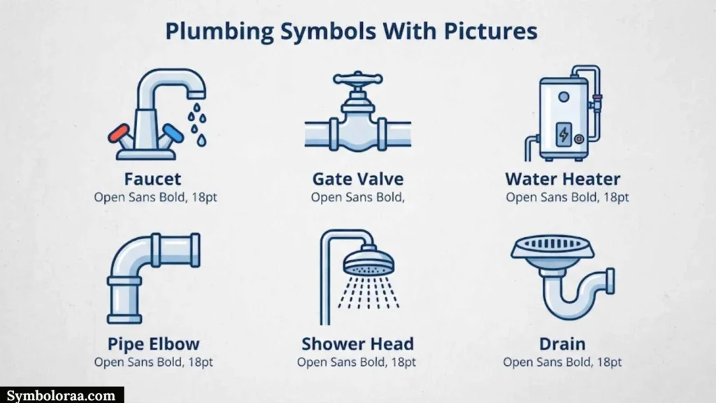
Plumbing symbols with pictures are easier to understand because the reader can compare the simplified drawing symbol with the physical plumbing component.
Common plumbing fixtures represented on plans include:
- Toilet or WC — Water closet.
- Lavatory — Bathroom sink.
- Kitchen sink — Sink used in a kitchen area.
- Bathtub — Tub fixture.
- Shower — Shower fixture.
- Floor drain — Drain installed at floor level.
- Hose bibb — Outdoor or utility water outlet.
- Cleanout — Access point for drainage maintenance.
- Water heater — Equipment used for heating domestic water.
- Floor sink — Receptor commonly used for indirect drainage.
- Service sink — Utility or janitor sink.
A plumbing drawing usually simplifies these objects rather than showing realistic pictures. The symbol communicates the component while a label, tag, schedule, or legend provides additional information.
When studying plumbing symbols from an image or drawing, compare three things:
- The shape of the symbol
- The abbreviation or tag beside it
- The project’s plumbing legend
This method is more reliable than memorizing a symbol from an unrelated drawing because different standards and projects can use different conventions.
For example, a toilet symbol may look slightly different between drawing libraries, but its fixture tag and legend can make its intended meaning clear.
Plumbing Symbols Valves
Valve symbols show where water or another fluid can be isolated, controlled, regulated, or prevented from flowing in the wrong direction.
Common valve types found on plumbing drawings include:
| Valve | Common Abbreviation | Main Function |
| Gate Valve | GV | Isolation |
| Globe Valve | GLV | Flow regulation |
| Angle Valve | AV | Shutoff at a change in direction |
| Ball Valve | BV | Quick isolation |
| Butterfly Valve | BFV | Isolation or control |
| Check Valve | CV | Prevents reverse flow |
| Plug Valve | PV | Isolation or flow control |
| Balancing Valve | BLV | System flow balancing |
| Solenoid Valve | — | Electrically operated control |
| Pressure-Reducing Valve | PRV | Reduces pressure |
| Pressure-Relief Valve | RV | Relieves excessive pressure |
| Temperature-Pressure-Relief Valve | TPV | Protects against excessive temperature and pressure |
| Thermostatic Mixing Valve | TMV | Controls mixed-water temperature |
| Backflow Preventer | RZBP | Helps protect against backflow |
These valve types and abbreviations are included in ASPE’s standard plumbing and piping symbol references.
Valve symbols are especially important because two valves can perform very different jobs. A check valve is concerned with preventing reverse flow, while a pressure-reducing valve changes downstream pressure.
Always check the valve abbreviation and project legend before identifying a valve from its graphic shape alone.
Plumbing Symbols Legend
A plumbing symbols legend is the reference key for the symbols and abbreviations used throughout a drawing set. It can appear on the plumbing sheet itself or as part of a broader drawing legend.
A typical plumbing legend may identify:
- Water-supply piping
- Sanitary drainage
- Storm drainage
- Vent piping
- Plumbing fixtures
- Valves
- Cleanouts
- Floor drains
- Hose bibbs
- Riser symbols
- Flow arrows
- Pipe connections
- Equipment
- Abbreviations
The legend is one of the most important parts of a plumbing drawing because it tells you what the designer intended each symbol to represent.
Common Plumbing Legend Abbreviations
CW — Cold water
HW — Hot water
HWR — Hot-water return
V — Vent
SS — Soil, waste, or sanitary sewer
SD — Storm drain
FD — Floor drain
CO — Cleanout
FCO — Floor cleanout
WCO — Wall cleanout
HB — Hose bibb
POC — Point of connection
PRV — Pressure-reducing valve
CV — Check valve
ASPE specifically states that standardized plumbing symbols are provided for drawing preparation, while also warning that some agencies, industry groups, and clients may have project-specific requirements.
That is why an online plumbing symbols chart should be used as a learning aid, not as a replacement for the actual project legend.
Plumbing Symbols Chart
A plumbing symbols chart gives readers a quick way to find commonly used symbols and abbreviations.
| Category | Symbol / Abbreviation | Meaning |
| Water Supply | CW | Cold water |
| Water Supply | HW | Hot water |
| Water Return | HWR | Hot-water return |
| Tempered Water | TW | Tempered water |
| Drainage | SS | Soil, waste, or sanitary sewer |
| Drainage | SD | Storm drain |
| Drainage | FD | Floor drain |
| Vent | V | Plumbing vent |
| Access | CO | Cleanout |
| Access | FCO | Floor cleanout |
| Access | WCO | Wall cleanout |
| Fixture | HB | Hose bibb |
| Valve | GV | Gate valve |
| Valve | GLV | Globe valve |
| Valve | BV | Ball valve |
| Valve | CV | Check valve |
| Valve | PRV | Pressure-reducing valve |
| Valve | RV | Pressure-relief valve |
| Connection | POC | Point of connection |
| Equipment | WHA | Water hammer arrester |
| Control | FS | Flow switch |
| Control | PS | Pressure switch |
| Air | AAV | Automatic air vent |
| Drainage | D | Indirect drain |
ASPE’s symbol tables also include components such as water hammer arresters, pressure gauges, automatic air vents, riser indicators, pipe branches, cleanouts, drains, and flow-direction indicators.
For students, apprentices, estimators, and anyone learning blueprint reading, a chart like this can be useful for quick revision.
Plumbing Symbols On Blueprints
Plumbing symbols on blueprints show how plumbing components are positioned within a building and how different parts of the system connect.
A plumbing blueprint may contain:
- Water-supply lines
- Sanitary drainage
- Vent piping
- Storm drainage
- Plumbing fixtures
- Valves
- Cleanouts
- Floor drains
- Pipe sizes
- Fixture tags
- Flow arrows
- Riser connections
- Equipment
- Points of connection
When reading a blueprint, start with the drawing title, notes, scale, and legend. Then identify the major plumbing systems before tracing individual fixtures.
For example, a bathroom drawing may contain a toilet, lavatory, shower, floor drain, cold-water line, hot-water line, sanitary drainage, and vent connection. The symbols allow all of this information to fit into a relatively small drawing.
A plumbing plan can also show the location and type of piping and fittings used for a rough-in. Educational plumbing guidance describes a residential plumbing plan as a two-dimensional plan-view drawing developed from the architectural floor plan.
Bluebeam Plumbing Symbols
Bluebeam is widely used for reviewing and marking up PDF construction drawings. When plumbing drawings are opened in Bluebeam, the software can be used to review symbols, add markups, measure drawings, and coordinate information.
However, Bluebeam does not automatically determine what a plumbing symbol means. The original drawing legend remains the authority for that project.
A practical Bluebeam workflow for plumbing drawings is:
- Open the correct plumbing sheet.
- Find the project legend.
- Identify the fixture and valve symbols.
- Review pipe labels and abbreviations.
- Use markups to identify issues or required changes.
- Use consistent markup labels for repeated components.
- Confirm drawing scale before taking measurements.
- Compare the plumbing plan with architectural and mechanical drawings when coordination is required.
Custom tool sets can also help users organize frequently used markup symbols. This can be useful for review work, estimating, coordination, and construction documentation.
The important distinction is that a Bluebeam markup is a review tool, while a plumbing symbol printed on the original construction drawing communicates the designer’s intended information.
Plumbing Symbols On Plans
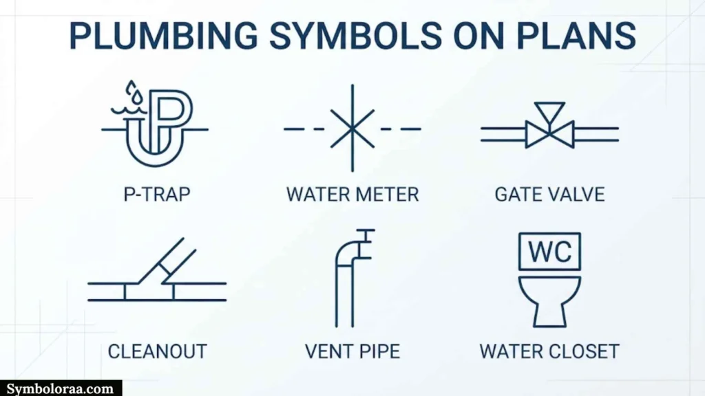
Plumbing symbols on plans show the location and relationship of fixtures, piping, valves, drains, vents, and other components from a plan-view perspective.
A plumbing plan is generally read from above. This makes it useful for understanding the horizontal arrangement of plumbing components.
For example, a bathroom plan could contain:
- WC — Water closet
- LAV — Lavatory
- SH — Shower
- FD — Floor drain
- CW — Cold water
- HW — Hot water
- V — Vent
- CO — Cleanout
Do not look at each symbol separately. Follow the lines connecting the components. This helps you understand where water enters the system, where wastewater leaves, and where vent piping connects.
Plan drawings also use symbols to indicate vertical piping. A pipe may rise to another floor, drop to a lower level, or connect to a vertical stack. The exact graphic convention should be checked against the project’s legend.
Residential DWV plans commonly show fixture locations, stacks, horizontal branches, and fixture drains. Educational plumbing material explains that plan views provide a two-dimensional representation of the piping system, while vertical pipes are represented through their locations and related symbols.
Isometric Plumbing Symbols
Isometric plumbing symbols are used in drawings that represent piping in a three-dimensional or axonometric style. They are particularly useful for understanding how horizontal and vertical pipes connect.
An isometric plumbing drawing may show:
- Vertical risers
- Horizontal branches
- Fixture connections
- Drainage pipes
- Vent piping
- Water-supply piping
- Pipe sizes
- Flow direction
- Rises and drops
- Branch connections
- Changes in elevation
ASPE’s plumbing symbol references include specific representations for riser up, riser down, rise or drop, branch connections, pipe elevation changes, and flow direction.
How To Read An Isometric Plumbing Drawing
Start with the main riser or primary pipe. Then follow each branch toward the connected fixture.
Pay attention to:
- Where a pipe changes direction
- Where a pipe rises or drops
- Which branches connect to the main line
- Where fixtures connect
- Which direction flow arrows indicate
- How different floors are connected
Isometric drawings are especially helpful when a simple plan view does not clearly communicate vertical relationships. Training material on domestic water systems also describes isometrics as a way to show piping layouts axonometrically, including water and gas lines in residential buildings.
Architectural Plumbing Symbols
Architectural plumbing symbols allow plumbing fixtures and basic plumbing information to be represented clearly on architectural drawings.
Common architectural plumbing components include:
- Toilets
- Lavatories
- Sinks
- Bathtubs
- Showers
- Floor drains
- Hose bibbs
- Water heaters
- Plumbing equipment
- Fixture connections
- Drainage points
An architectural floor plan generally focuses on the location and arrangement of rooms, walls, doors, fixtures, and other building elements. Detailed plumbing drawings can then provide additional information about pipe routing, sizing, valves, drainage, and venting.
Fixture symbols are particularly useful during coordination. For example, an architect can see where a bathroom fixture is located, while a plumbing designer can use that location to develop the related supply and drainage system.
Plumbing Symbols For Architectural Drawings
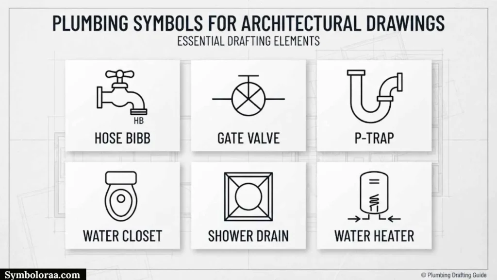
Plumbing symbols for architectural drawings should be clear, consistent, and easy to distinguish at the final drawing scale.
A well-organized architectural drawing may include:
- Plumbing fixture symbols
- Fixture tags
- Plumbing abbreviations
- Water-supply lines
- Drainage lines
- Vent indicators
- Valve symbols
- Cleanout symbols
- Floor-drain symbols
- Riser indicators
- Equipment tags
Consistency is particularly important when the same fixture appears in several rooms. A toilet, lavatory, or floor drain should not suddenly use an unrelated symbol without an explanation in the legend.
Plumbing Symbols And Fixture Tags
A fixture symbol tells you what the component is, while a fixture tag can connect that component to a fixture schedule.
A schedule may provide additional information such as:
- Fixture type
- Manufacturer requirements
- Model information
- Connection sizes
- Installation notes
- Special requirements
This combination keeps the architectural drawing readable while allowing more detailed information to remain in the schedules and specifications.
Residential Plumbing Symbols
Residential plumbing symbols are used on house, apartment, townhouse, and other residential plumbing drawings. They represent fixtures, water services, drainage, vents, valves, and equipment.
Common residential plumbing symbols and abbreviations include:
| Residential Component | Common Identification |
| Toilet | WC |
| Lavatory | LAV |
| Kitchen Sink | KS |
| Shower | SH |
| Bathtub | Tub symbol |
| Floor Drain | FD |
| Hose Bibb | HB |
| Cleanout | CO |
| Floor Cleanout | FCO |
| Cold Water | CW |
| Hot Water | HW |
| Hot-Water Return | HWR |
| Vent | V |
| Pressure-Reducing Valve | PRV |
| Check Valve | CV |
| Water Heater | Equipment tag |
A residential plumbing plan can show the relationship between bathrooms, kitchens, utility rooms, water heaters, exterior hose connections, and the main plumbing lines.
For example, water from the main service may feed a water heater and cold-water branches. The hot-water system can then supply fixtures such as lavatories, showers, bathtubs, and kitchen sinks. Wastewater travels through drainage piping, while vent piping supports the drainage system.
For multi-story homes, risers and vertical stacks become especially important. An isometric or riser diagram can make these connections easier to understand than a single floor plan.
Common Residential Plumbing Areas
Bathroom: Toilet, lavatory, shower, bathtub, floor drain, hot water, cold water, drainage, and vent connections.
Kitchen: Kitchen sink, dishwasher connection, water supply, waste connection, and related drainage.
Laundry: Washing-machine connections, standpipe, hot and cold water, and drainage.
Utility Area: Water heater, shutoff valves, pressure-control components, and service connections.
Exterior: Hose bibbs or wall hydrants and their water-supply connections.
The exact symbols used for these components should always be verified against the drawing legend and applicable project requirements.
FAQ
What are plumbing symbols used for?
Plumbing symbols are used to represent fixtures, pipes, valves, drains, vents, equipment, connections, and other components on technical drawings.
Are plumbing symbols universal?
No. Many plumbing symbols and abbreviations are widely recognized, but drawing conventions can vary between standards, projects, consultants, and authorities. The project legend should be checked first.
What does CW mean on a plumbing drawing?
CW commonly means cold water and identifies cold-water supply piping. The exact abbreviation should still be confirmed with the drawing legend.
What does CO mean on a plumbing plan?
CO commonly means cleanout, an access point provided for inspection, maintenance, or cleaning of drainage piping. More specific abbreviations such as FCO and WCO can identify floor and wall cleanouts.
How do I read plumbing symbols on a blueprint?
Start with the project legend, then identify the drawing type, pipe labels, fixtures, valves, flow arrows, and riser information. Follow connected piping to understand how the system works.
Conclusion
Plumbing symbols provide a compact way to communicate complicated plumbing systems on plans, blueprints, architectural drawings, and isometric diagrams. Common abbreviations such as CW, HW, HWR, V, FD, CO, and POC can help readers quickly identify important components and services.
The most reliable way to interpret a symbol is to consider its graphic shape together with its abbreviation, location, connected piping, and project legend. Valve symbols, fixture symbols, drainage symbols, and riser indicators each provide a different part of the overall system information.
If you are studying residential plumbing, reviewing architectural drawings, preparing construction documents, or using Bluebeam to mark up plans, learning the common symbols makes technical drawings much easier to understand. Keep the project-specific legend beside you whenever accuracy matters.

I’m Madison Reed, a contemporary American author who writes about love, family, friendship, and second chances. I’m fascinated by the choices that shape our lives and the moments that change us forever. My goal is to create honest, emotional stories with characters readers can connect with long after finishing each book.
Three Books:
When We Find Our Way
The Things We Never Said
Summer in September
 Jackson Miller