Electric circuit symbols are standardized drawings used to represent electrical and electronic components in circuit diagrams. Instead of drawing the physical shape of a battery, resistor, switch, motor, or diode, engineers and students use simple symbols to show what each component does and how the parts are connected.
Understanding electric circuit symbols makes circuit diagrams much easier to read. Whether you are a student learning basic electricity, an electrician reading a schematic, an electronics technician troubleshooting a board, or an engineer designing a control system, these symbols provide a common visual language.
This guide explains the most common electrical and electronic symbols, what they mean, how they are used, how to read them in real circuits, and how international standards such as IEC 60617 and ANSI/IEEE conventions affect their appearance.
Quick Answer: What Are Electric Circuit Symbols?
Electric circuit symbols are standardized graphical representations of electrical components and functions used in schematic diagrams.
For example:
| Component | Common Symbol Idea | Main Function |
| Wire | Straight line | Carries electrical current |
| Cell | Long and short parallel lines | Provides electrical energy |
| Battery | Multiple cell symbols | Provides electrical energy |
| Resistor | Rectangle or zigzag | Limits current |
| Variable resistor | Resistor with an arrow | Adjusts resistance |
| Capacitor | Two plates | Stores electrical charge |
| Inductor | Coil | Stores energy in a magnetic field |
| Switch | Break in a conductor with movable contact | Opens or closes a circuit |
| Fuse | Protective element | Opens the circuit during excessive current |
| Diode | Diode symbol with a cathode bar | Allows current primarily in one direction |
| LED | Diode symbol with outward arrows | Produces light |
| Motor | Circle with M | Converts electrical energy into mechanical motion |
| Lamp | Circle with lamp marking | Produces light |
| Ammeter | Circle with A | Measures current |
| Voltmeter | Circle with V | Measures voltage |
| Ground | Ground symbol | Provides a reference or grounding connection |
The exact graphical appearance can vary between standards and drawing systems, so a circuit symbol should be interpreted together with the diagram’s standard and context.
Why Electric Circuit Symbols Matter
They Make Complex Circuits Easier to Understand
A physical electrical system may contain hundreds or thousands of individual parts. Drawing every component as it physically looks would make a schematic difficult to read.
Symbols simplify the drawing.
For example, a resistor does not need to be drawn as a real cylindrical component. A standardized resistor symbol immediately tells the reader that the component provides electrical resistance.
This allows a complicated circuit to be represented clearly on a single page.
They Create a Common Technical Language
Electrical systems are often designed, installed, repaired, and tested by different people.
A standardized symbol helps these people understand the same circuit without needing to know the original designer personally.
This is particularly important in:
- Electrical engineering
- Electronics
- Industrial automation
- Building wiring
- Control systems
- Telecommunications
- Automotive electrical systems
- Manufacturing
- Electrical maintenance
- Printed circuit board design
They Show Function Rather Than Physical Appearance
A schematic symbol normally tells you what a component does, not exactly what it looks like.
For example, a motor symbol represents the function of converting electrical energy into mechanical motion. The actual motor could be large, small, cylindrical, square, brushless, brushed, AC, or DC.
The schematic focuses on electrical function and connections.
Common Electric Circuit Symbols at a Glance
The following groups cover the symbols most commonly encountered in basic electrical and electronic diagrams.
| Category | Common Components |
| Conductors | Wire, junction, terminal |
| Power Sources | Cell, battery, DC supply, AC supply |
| Passive Components | Resistor, capacitor, inductor |
| Switching | Open switch, closed switch, push button, selector switch |
| Protection | Fuse, circuit breaker |
| Semiconductors | Diode, LED, Zener diode, transistor |
| Energy Conversion | Motor, generator, transformer |
| Output Devices | Lamp, buzzer, bell, speaker |
| Measurement | Ammeter, voltmeter, ohmmeter |
| Control | Relay, contactor |
| Connection | Ground, earth, chassis connection |
| Communication | Antenna |
Wire and Connection Symbols
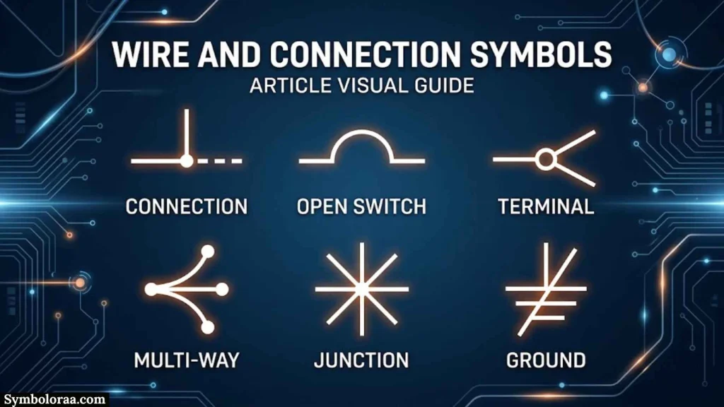
Wire Symbol
A wire is normally represented by a simple straight line.
The line shows an electrical conductor connecting one point in a circuit to another.
For example:
Battery ───── Switch ───── Lamp
The line itself does not necessarily tell you the physical size, material, or route of the conductor. Those details may appear in other documentation.
Junction or Connected Wires
When multiple conductors meet at an electrical connection point, the diagram may use a junction indication such as a dot.
│
──────●──────
│
The point indicates that the conductors are electrically connected.
Crossing Wires
Two lines crossing on a schematic should not automatically be assumed to be connected.
Depending on the drawing convention, a connection may be shown with a junction dot or another explicit connection method.
This is an important detail because assuming that every crossing represents a connection can completely change how a circuit operates.
Power Source Symbols
Power sources provide electrical energy to a circuit.
Cell Symbol
A cell is represented using two parallel lines of unequal length. The longer line represents the positive terminal and the shorter line represents the negative terminal in common schematic conventions.
A cell provides a potential difference that can drive current through a circuit.
Battery Symbol
A battery is commonly represented by multiple cell symbols arranged together.
Conceptually:
— | | | | | | —
The repeated long-and-short-line pattern distinguishes a battery from a single cell.
In real electrical systems, a battery may contain many cells even though the schematic uses a simplified symbol.
DC Supply
A direct-current supply is commonly identified using a DC supply symbol or polarity markings.
DC means the electrical polarity remains oriented in one direction under normal operation.
Examples include:
- Batteries
- USB power supplies
- Many electronic power supplies
- Solar-powered systems
- DC control circuits
AC Supply
Alternating-current sources are represented using symbols that indicate an AC source or supply.
AC systems are common in:
- Household electrical systems
- Industrial power
- Electrical distribution
- Motors and generators
- Power transmission
The exact supply symbol can depend on the diagram standard.
Resistor Circuit Symbols
Fixed Resistor
A resistor limits or controls current and produces a voltage drop according to the circuit conditions.
Two major graphical conventions are common:
- IEC-style rectangular resistor symbol
- Older or ANSI-style zigzag resistor symbol
This is a useful example of why recognizing the function is more important than memorizing one visual version.
A resistor may be used for:
- Current limiting
- Voltage division
- Biasing
- Pull-up or pull-down circuits
- Signal conditioning
- Heating
Variable Resistor
A variable resistor includes an adjustment indication, commonly represented by an arrow.
Its resistance can be changed to control current or voltage in a circuit.
Typical applications include:
- Adjustable controls
- Tuning circuits
- Calibration
- Sensor interfaces
- Motor control applications
Potentiometer
A potentiometer is a three-terminal adjustable resistor. Its moving contact allows the output voltage to be varied across part of the resistance.
Common examples include:
- Volume controls
- Display brightness controls
- Position controls
- User-adjustable electronic settings
Capacitor Symbols
Fixed Capacitor
A capacitor is commonly represented by two plates separated by a small gap.
Capacitors store electrical energy in an electric field.
They are used for:
- Filtering
- Smoothing
- Coupling signals
- Timing
- Energy storage
- Noise reduction
Polarized Capacitor
A polarized capacitor has a defined positive and negative orientation.
Electrolytic capacitors are a common example.
Incorrect polarity can damage the component, so polarity markings are important when reading or building a circuit.
Variable Capacitor
A variable capacitor includes an adjustment indication and allows its capacitance to be changed.
Variable capacitors have been used in applications such as:
- Radio tuning
- Frequency adjustment
- Resonant circuits
- Specialized RF equipment
Inductor and Coil Symbols
An inductor is commonly shown as a series of curved loops representing a coil.
An inductor stores energy in a magnetic field when current flows through it.
Inductors are commonly found in:
- Filters
- Power supplies
- Transformers and magnetic circuits
- Oscillators
- Radio-frequency circuits
- Energy-conversion systems
The number of loops in a drawing is normally symbolic rather than a literal representation of the number of turns in the physical coil.
Switch Symbols
Switches control whether an electrical path is open or closed.
Open Switch
An open switch represents a broken electrical path.
──────/ ──────
Because the path is open, current cannot normally flow through that branch.
Closed Switch
A closed switch completes the electrical path.
───────┄──────
The exact graphical appearance depends on the drawing convention, but the important idea is that the contacts are connected.
Push Button
A push-button symbol represents a switch operated by pressing it.
Push buttons may be:
- Normally open
- Normally closed
They are widely used in control panels, machines, alarms, and electronic devices.
Selector Switch
A selector switch allows one or more circuit paths to be selected.
It is commonly used in:
- Control panels
- Industrial machinery
- Operating-mode selection
- Electrical control circuits
Fuse and Circuit Protection Symbols
Fuse
A fuse protects an electrical circuit against excessive current.
When the current becomes high enough, the fuse element opens the circuit.
A fuse symbol represents the protective device in the schematic rather than its physical appearance.
Fuses are commonly used in:
- Household equipment
- Automotive systems
- Electronic devices
- Industrial equipment
- Power distribution
Circuit Breaker
A circuit breaker is a resettable protective switching device.
Unlike a conventional fuse, a circuit breaker can generally be reset after it trips, depending on its design.
Circuit breakers are widely used in:
- Distribution boards
- Industrial systems
- Building electrical installations
- Control panels
Protection symbols matter because they tell a technician where the circuit is designed to interrupt power under abnormal conditions.
Diode Circuit Symbols
Standard Diode
A diode is a semiconductor device designed to conduct current primarily in one direction.
The standard diode symbol identifies the two terminals:
- Anode
- Cathode
The cathode is associated with the bar side of the symbol.
A simplified representation is often written as:
───|>|───
In this text representation, the final vertical bar represents the cathode. Actual schematic drawings use the standardized graphical symbol rather than this ASCII approximation.
LED Symbol
An LED, or light-emitting diode, uses a diode symbol combined with arrows pointing outward to show emitted light.
LEDs are used in:
- Indicators
- Displays
- Lighting
- Signaling systems
- Optical communication
Photodiode Symbol
A photodiode is represented using a diode symbol with arrows directed toward the device to indicate incoming light.
Photodiodes are used for light detection and sensing.
Zener Diode
A Zener diode uses a modified diode symbol with a distinctive cathode marking.
It is commonly used for:
- Voltage regulation
- Voltage reference circuits
- Protection
- Clamping applications
Transistor Symbols
Transistors are semiconductor devices used for switching, amplification, and signal control.
BJT Symbol
A bipolar junction transistor, or BJT, has three terminals:
- Base
- Collector
- Emitter
Common BJT types include:
- NPN
- PNP
The transistor symbol helps identify the terminal arrangement and device type.
MOSFET Symbol
A MOSFET is a field-effect transistor with terminals commonly identified as:
- Gate
- Drain
- Source
MOSFETs are widely used in:
- Switching power supplies
- Motor controllers
- Digital electronics
- Power electronics
- Amplifier circuits
Different transistor symbols contain details that help identify polarity, terminal function, and device type.
Transformer Symbol
A transformer is represented using two or more coils with magnetic coupling indicated between them.
A simplified transformer representation looks conceptually like:
Coil || Coil
Transformers transfer electrical energy between circuits through electromagnetic induction.
They can be used to:
- Increase voltage
- Decrease voltage
- Provide electrical isolation
- Match impedance
- Transfer AC power
The physical transformer may look very different from its schematic symbol.
Motor and Generator Symbols
Motor
A motor converts electrical energy into mechanical motion.
A common simplified symbol uses a circle containing an M.
Motors are found in:
- Fans
- Pumps
- Machines
- Vehicles
- Robotics
- Industrial equipment
Generator
A generator converts mechanical energy into electrical energy.
Its schematic representation identifies its electrical function rather than showing its physical construction.
Generators are used in:
- Power stations
- Backup power systems
- Portable generators
- Renewable-energy systems
Lamp and Light Symbols
A lamp converts electrical energy into visible or other forms of light.
A common schematic representation uses a circle with a lamp marking or filament-style indication.
Lamps appear in:
- Lighting circuits
- Indicator circuits
- Control panels
- Test equipment
An LED should not automatically be treated as the same component as a generic lamp. An LED is a semiconductor device with different electrical characteristics.
Measuring Instrument Symbols
Ammeter
An ammeter measures electrical current.
Its symbol commonly contains the letter A inside a circle.
An ammeter is normally connected in series with the part of the circuit whose current is being measured.
Voltmeter
A voltmeter measures potential difference, or voltage.
Its symbol commonly contains the letter V inside a circle.
A voltmeter is normally connected across the component or circuit section being measured.
Ohmmeter
An ohmmeter measures electrical resistance.
Its symbol may use an Ω marking.
Multimeter
A multimeter combines multiple measurement functions in one instrument.
Depending on the model, it may measure:
- Voltage
- Current
- Resistance
- Continuity
- Capacitance
- Frequency
- Diode characteristics
The schematic symbol or notation used depends on the specific diagram and standard.
Ground and Earth Symbols
Ground-related symbols can look similar but do not always mean exactly the same thing.
Circuit Ground
Circuit ground can provide a reference point from which voltages in a circuit are described.
For example, a voltage may be specified as 5 V relative to circuit ground.
Protective Earth
Protective earth is associated with electrical safety and the connection intended to protect people and equipment from dangerous fault voltages.
Chassis Ground
Chassis ground indicates a connection to a conductive equipment enclosure or chassis.
These concepts may be connected in some systems, but they should not automatically be treated as interchangeable.
Relay and Contactor Symbols
Relay
A relay is an electrically controlled switching device.
Its schematic representation commonly shows:
- A coil
- One or more contacts
The coil controls the contacts through electromagnetic action or another internal mechanism.
Relays are useful when a low-power control circuit needs to operate a separate circuit.
Contactor
A contactor is designed for switching power circuits, particularly in industrial applications.
Contactors are commonly used for:
- Motors
- Heaters
- Industrial machinery
- Large electrical loads
Buzzer, Bell, and Speaker Symbols
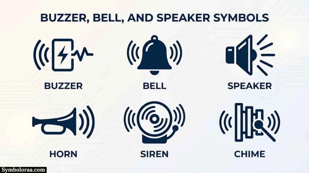
Buzzer
A buzzer converts electrical signals into an audible sound.
It is often used for:
- Alarms
- Notifications
- Warning systems
- Control panels
Bell
A bell symbol represents an electrically operated audible signaling device.
Speaker
A speaker converts an electrical signal into sound.
Speaker symbols are common in:
- Audio equipment
- Intercoms
- Communication systems
- Electronic devices
Antenna and Sensor Symbols
Antenna
An antenna symbol represents a device used to transmit or receive electromagnetic signals.
Antennas appear in:
- Radio systems
- Wireless communication
- Television
- Navigation systems
- Communication equipment
Sensor
Sensors detect physical conditions and convert them into electrical information or an electrical response.
Examples include:
- Temperature sensors
- Light sensors
- Pressure sensors
- Motion sensors
- Proximity sensors
The exact symbol depends on the type of sensor and the standard being used.
Electrical Symbols by Function
Grouping symbols by function is often easier than memorizing them alphabetically.
| Function | Examples |
| Supply Energy | Cell, battery, AC source, DC source |
| Conduct Current | Wire, terminal, connector |
| Limit Current | Resistor, fuse |
| Store Energy | Capacitor, inductor |
| Control Current | Switch, relay, transistor |
| Protect Circuit | Fuse, circuit breaker, Zener diode |
| Convert Energy | Motor, generator, transformer |
| Produce Light | Lamp, LED |
| Produce Sound | Buzzer, bell, speaker |
| Measure | Ammeter, voltmeter, ohmmeter |
| Detect Conditions | Sensors, photodiodes |
| Provide Reference | Ground, earth, chassis connection |
Thinking in functional groups makes unfamiliar symbols easier to understand.
How to Read an Electric Circuit Diagram
Reading a circuit diagram is more than identifying individual symbols. You also need to understand the connections between them.
Start With the Power Source
Find the battery, power supply, generator, or other source.
Ask:
- Where does electrical energy enter?
- What are the positive and negative terminals?
- Is the supply AC or DC?
- What voltage is shown?
Follow the Conductors
Trace the wires from the source through the circuit.
Look for:
- Junctions
- Switches
- Protection devices
- Loads
- Return paths
- Ground connections
Identify the Main Load
The load is the part that consumes or converts electrical energy.
Examples include:
- Lamp
- Motor
- Heater
- Resistor
- Electronic circuit
Check the Control Components
Look for switches, relays, transistors, and other devices that control current.
Check Protection Devices
Identify fuses, circuit breakers, and other protective components.
This can help you understand where the circuit is designed to respond to abnormal current or fault conditions.
Practical Electric Circuit Examples
Battery, Switch, and Lamp
A basic circuit can contain:
Battery → Switch → Lamp → Battery
When the switch is open, the circuit path is broken and the lamp remains off.
When the switch is closed, the circuit path is completed and current can flow through the lamp.
This simple example teaches three important ideas:
- A source provides electrical energy.
- A switch controls the path.
- A lamp acts as a load.
Battery, Resistor, and LED
A common educational circuit is:
Battery → Resistor → LED → Battery
The resistor limits current through the LED.
The LED converts part of the electrical energy into light.
This example demonstrates why symbols should be understood as a system rather than as isolated pictures.
Fuse and Load
A protected load may be represented conceptually as:
Supply → Fuse → Switch → Load → Return
The fuse is placed so excessive current can interrupt the circuit and protect downstream wiring or equipment.
Motor Control Circuit
A simple motor control system may include:
Control Switch → Relay/Contactor → Motor
The control circuit operates the relay or contactor, while the controlled contacts switch power to the motor.
Industrial diagrams may be much more detailed, but the same functional relationship remains.
Electric Circuit Symbols vs Electronic Symbols
The terms electric circuit symbols and electronic symbols are often used interchangeably in general searches, but there is a useful distinction.
Electrical diagrams commonly include components such as:
- Switches
- Fuses
- Motors
- Transformers
- Lamps
- Circuit breakers
Electronic schematics commonly include:
- Diodes
- Transistors
- Integrated circuits
- Capacitors
- Resistors
- Operational amplifiers
- Sensors
There is significant overlap because many electronic components are electrical components too.
The difference is usually based on the type of system being represented rather than a strict dividing line.
Schematic Symbols vs Wiring Symbols
A schematic diagram shows the logical and electrical relationships between components.
A wiring diagram focuses more directly on how conductors and connections are physically arranged or terminated.
For example, a schematic may show:
Supply → Switch → Motor
A wiring document may additionally show:
- Terminal numbers
- Wire numbers
- Cable routes
- Connector pins
- Physical locations
A schematic therefore should not automatically be treated as an installation drawing.
IEC vs ANSI and IEEE Circuit Symbols
IEC Symbols
IEC 60617 is the major international reference for graphical symbols used in electrotechnical diagrams. The IEC database contains a large collection of standardized symbols covering areas such as conductors, passive components, semiconductors, electrical energy systems, measuring equipment, signaling devices, and installation diagrams.
Using standardized symbols helps different professionals interpret technical documentation consistently.
ANSI and IEEE Conventions
ANSI and IEEE publications have also provided graphical symbol conventions for electrical, electronic, logic, wiring, and related diagrams.
Some symbols used in North American educational material and technical documentation may therefore look different from IEC versions.
Why Symbol Differences Matter
A resistor is a good example.
One drawing may use a rectangle:
───[ ]───
Another may use a zigzag:
───/\/\/───
Both can represent a resistor.
The important lesson is:
Do not assume that a different-looking symbol represents a different component. Check the diagram’s standard and context.
For professional work, use the symbol standard specified by the project, organization, or applicable technical documentation.
History and Standardization of Circuit Symbols
Early electrical diagrams did not have one universal graphical language. Different engineers, manufacturers, countries, and technical communities could use different representations.
As electrical technology expanded, standardization became increasingly important.
Organizations developed conventions to make technical drawings easier to exchange and interpret.
Modern electrical documentation uses standardized symbol systems to reduce ambiguity.
IEC 60617 is particularly important internationally. It provides graphical symbols for electrotechnical diagrams and is maintained as a dedicated international symbol database.
Standardization matters because an electrical drawing may be created by one organization, manufactured by another, installed by a third party, and maintained years later by technicians who were not involved in the original design.
How to Identify an Unknown Circuit Symbol
You do not always need to memorize every symbol.
Use this process when you encounter an unfamiliar symbol.
Step 1: Look at the Shape
Ask what basic form you see:
- Rectangle
- Circle
- Coil
- Parallel plates
- Arrow
- Switch contact
- Triangle-like semiconductor marking
- Repeated lines
Step 2: Look for Additional Markings
Letters and arrows can provide important clues.
Examples include:
- A for ammeter
- V for voltmeter
- M for motor
- Ω for resistance
- Arrows pointing outward for emitted light in an LED
- Arrows pointing inward for light-sensitive devices
Step 3: Check the Connections
The number of terminals can help identify a component.
For example:
- Two terminals may indicate a resistor, capacitor, diode, or lamp.
- Three terminals may suggest a transistor, potentiometer, or certain sensors.
- Multiple contacts may indicate a relay or switch arrangement.
Step 4: Examine the Surrounding Circuit
Context is often the strongest clue.
A symbol connected to an amplifier may have a different role from a similar-looking symbol used in a power-control circuit.
Step 5: Check the Drawing Standard
If the symbol still seems unfamiliar, determine whether the diagram follows:
- IEC conventions
- ANSI conventions
- IEEE conventions
- Manufacturer-specific documentation
- A specialized industry standard
Common Mistakes When Reading Circuit Symbols
Assuming Every Wire Crossing Is a Connection
Crossing lines can be misleading.
Always look for the connection convention used in the diagram.
Confusing a Schematic With Physical Wiring
A schematic explains electrical relationships. It may not show the physical position or routing of every wire.
Ignoring Polarity
Components such as batteries, LEDs, diodes, and polarized capacitors can require correct polarity.
Treating Ground and Earth as the Same Thing
Ground can refer to a circuit reference, while protective earth has a safety function. Chassis ground can refer to an equipment enclosure.
The actual relationship depends on the system.
Memorizing Only One Version of a Symbol
A symbol may have different graphical conventions.
Learning only one version can cause confusion when reading another standard.
Looking at Symbols Without Reading Labels
Reference designators, values, terminal numbers, and notes can provide information that the graphical symbol alone does not show.
How Students Can Memorize Electric Circuit Symbols
Students often try to memorize dozens of symbols individually. A functional approach is easier.
Start with five groups:
- Supply — cell, battery, power source
- Control — switch, relay, transistor
- Passive — resistor, capacitor, inductor
- Output — lamp, motor, speaker
- Protection and Measurement — fuse, breaker, ammeter, voltmeter
Then learn each component through three questions:
What does it look like?
What does it do?
Where is it used?
For example:
Resistor → limits current → used for current control and voltage division.
This creates a useful connection between the symbol and its purpose instead of relying only on visual memorization.
How Professionals Use Circuit Symbols
Electricians
Electricians may use symbols when reading:
- Building electrical drawings
- Control diagrams
- Distribution plans
- Wiring documentation
- Equipment schematics
Electrical Engineers
Electrical engineers use circuit symbols to design and analyze:
- Power systems
- Control systems
- Protection circuits
- Electrical equipment
- Industrial systems
Electronics Engineers and Technicians
Electronic schematics rely heavily on symbols for:
- Semiconductor devices
- Analog circuits
- Digital circuits
- Sensors
- Power supplies
- Communication circuits
CAD and Electrical Design Users
Electrical design software uses symbol libraries to create structured diagrams.
A CAD symbol may contain additional information beyond its visible shape, such as:
- Component data
- Connection points
- Reference designators
- Manufacturer information
- Electrical properties
This is why a professional CAD symbol is more than a simple picture.
Troubleshooting With Circuit Symbols
Circuit symbols can also help technicians diagnose problems.
Suppose a lamp does not turn on.
A technician can trace the diagram in this order:
Power Source
↓
Protection
↓
Switch
↓
Wiring
↓
Lamp
↓
Return Path
At each stage, ask whether the expected voltage, continuity, or control signal is present.
For an electronic circuit, the path may instead involve:
Power Supply
↓
Protection
↓
Switching/Control
↓
Signal Processing
↓
Output Device
The schematic provides a map for this process.
Electric Circuit Symbols in Software and Digital Schematics
Modern electrical and electronic design tools commonly use digital symbol libraries.
These tools may support:
- Schematic capture
- Electrical simulation
- PCB design
- Control-system documentation
- Wiring diagrams
- Automated reports
- Bill of materials
The software may enforce connection rules and component attributes, reducing errors that can occur when symbols are drawn manually.
However, software does not remove the need to understand the underlying symbols. A technically incorrect schematic can still be created if the designer selects the wrong component or connection.
Frequently Asked Questions
What Are the Most Common Electric Circuit Symbols?
The most common symbols include the wire, cell, battery, resistor, capacitor, inductor, switch, fuse, diode, LED, transistor, motor, lamp, ground, ammeter, and voltmeter.
These components appear frequently in educational circuits, electronic schematics, electrical control diagrams, and technical documentation.
What Does a Resistor Symbol Mean?
A resistor symbol represents a component that provides electrical resistance. Its main purposes include limiting current, creating voltage drops, and forming voltage-divider or biasing circuits.
The symbol may appear as a rectangle or zigzag depending on the convention being used.
What Does a Battery Symbol Mean?
A battery symbol represents a source of electrical energy made from one or more cells. It normally uses repeated long and short parallel lines.
The longer and shorter lines indicate polarity in common schematic conventions.
What Is the Symbol for a Switch?
A switch is represented by electrical contacts that can be shown in an open or closed position.
An open switch indicates a broken path, while a closed switch indicates a completed path.
What Is the Symbol for a Diode?
A diode symbol identifies a semiconductor device that primarily permits current in one direction. The cathode is identified by the bar side of the symbol.
Different diode types use modified symbols to indicate additional functions.
What Is the Difference Between a Diode and an LED Symbol?
An LED uses the basic diode symbol with additional outward-pointing arrows to represent emitted light.
A standard diode does not use those light-emission arrows.
What Does the Ground Symbol Mean?
A ground symbol identifies a designated reference or grounding connection. Its exact meaning depends on the diagram and may refer to circuit ground, protective earth, chassis ground, or another grounding function.
Are IEC and ANSI Circuit Symbols the Same?
Not always. Many symbols have equivalent meanings across standards, but their graphical appearance and conventions can differ.
Always check the standard used by the drawing when accuracy matters.
Why Do Some Resistors Look Different on Circuit Diagrams?
Different standards use different resistor representations. A rectangular resistor is common in IEC-style documentation, while a zigzag representation is widely encountered in North American and older diagrams.
Both can represent the same basic component.
Are Electric and Electronic Circuit Symbols Different?
There is considerable overlap. Electrical diagrams may focus more on power, switching, protection, and energy conversion, while electronic schematics often contain semiconductors and signal-processing components.
The distinction is based mainly on application and system type.
How Can I Learn Circuit Symbols Quickly?
Learn symbols by function rather than memorizing isolated shapes. Start with power sources, conductors, resistive components, switching devices, protection devices, semiconductors, loads, and measurement instruments.
For each symbol, learn its appearance, purpose, terminals, and common applications.
Key Takeaways
- Electric circuit symbols are graphical representations of electrical and electronic components.
- Symbols make complex circuit diagrams easier to read and communicate.
- A symbol normally represents a component’s electrical function rather than its physical appearance.
- Common symbols include resistors, capacitors, inductors, switches, batteries, diodes, LEDs, transistors, motors, lamps, and measuring instruments.
- Different standards can use different graphical representations for equivalent components.
- IEC 60617 is an important international reference for electrotechnical graphical symbols.
- ANSI and IEEE conventions are also encountered, particularly in North American technical documentation.
- A wire crossing does not always mean that the conductors are electrically connected.
- Ground, earth, and chassis connections should not automatically be treated as identical.
- Learning symbols by function and circuit context is more effective than memorizing shapes alone.
- Understanding symbols is essential for reading, designing, installing, and troubleshooting electrical and electronic systems.
Conclusion
Electric circuit symbols provide the visual language used to describe electrical and electronic systems in schematic diagrams. They simplify complex circuits by replacing physical components with standardized graphical representations that show their function and electrical relationships.
The most useful way to learn these symbols is to connect each one with its purpose. A resistor limits current, a capacitor stores electrical energy, a switch controls a path, a diode controls current direction, a motor converts electrical energy into motion, and a measuring symbol identifies what a meter is designed to measure.
It is also important to understand that symbols can vary between IEC, ANSI, IEEE, and other conventions. When working with professional documentation, always follow the standard specified for that project.
Once you understand the symbols, their functions, their connections, and the conventions behind them, even complex circuit diagrams become much easier to interpret.

I’m Madison Reed, a contemporary American author who writes about love, family, friendship, and second chances. I’m fascinated by the choices that shape our lives and the moments that change us forever. My goal is to create honest, emotional stories with characters readers can connect with long after finishing each book.
Three Books:
When We Find Our Way
The Things We Never Said
Summer in September
 Jackson Miller