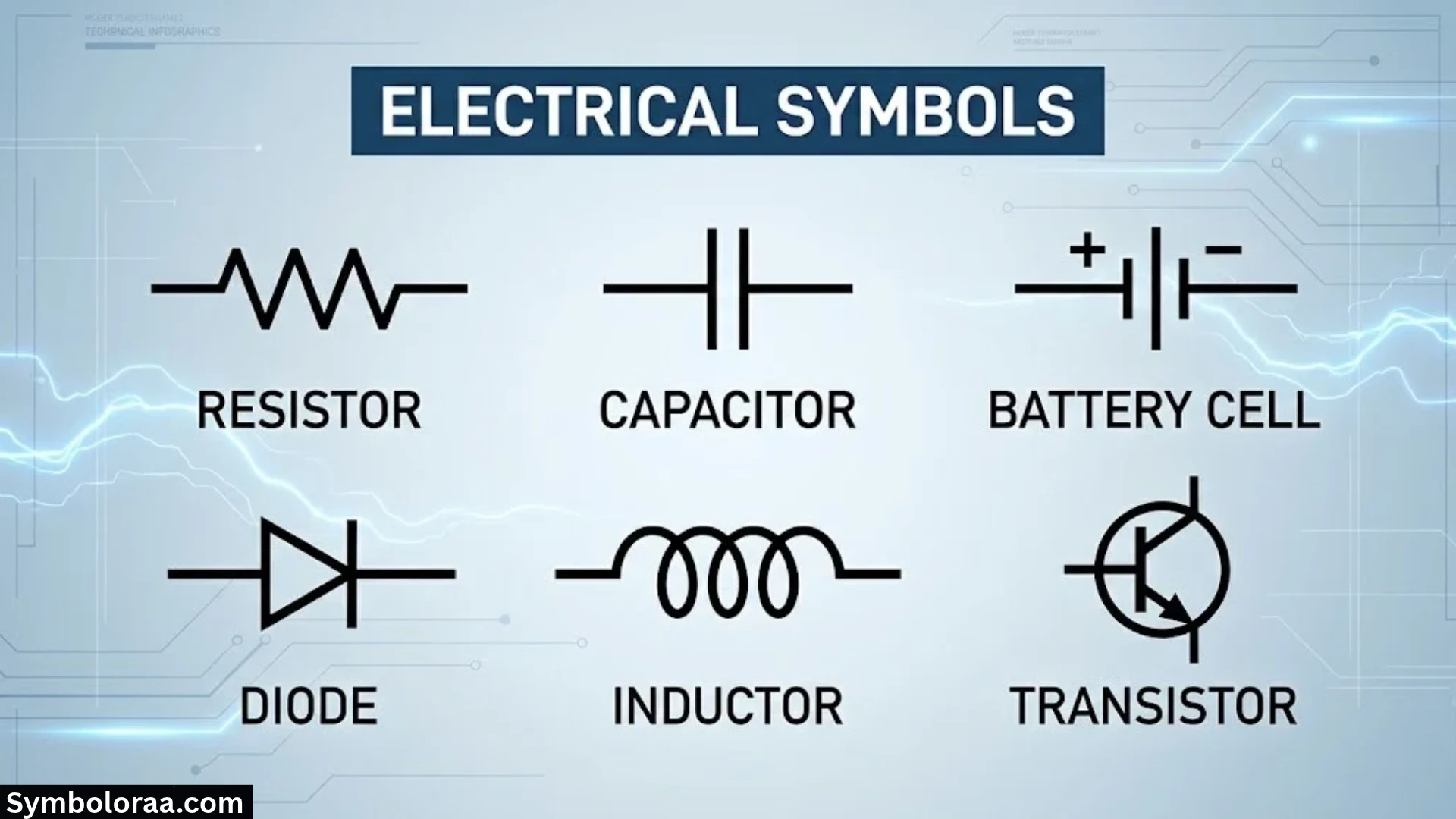
Electrical symbols make complicated electrical systems easier to understand. Whether you’re studying basic circuits, planning home wiring, or troubleshooting industrial equipment, these symbols help you identify components and follow their connections without studying every physical detail.
An electrical diagram might contain dozens or even hundreds of symbols. A simple switch can control a lamp, while a more complex drawing might show transformers, circuit breakers, motors, relays, and protective devices working together. Once you understand the symbols, the entire system becomes easier to follow.
This guide covers electrical symbols and their meanings, common component symbols, different types of electrical diagrams, and practical techniques for reading electrical drawings. You’ll also learn how electrical standards affect symbol design and how engineers use these symbols in residential, commercial, and industrial applications.
What Are Electrical Symbols?
Electrical symbols are graphical representations of electrical and electronic components used in circuit diagrams, wiring plans, and engineering drawings. Each symbol communicates information about a component or connection without requiring a detailed picture of the physical device.
For example, a resistor symbol identifies a component that limits current or produces a voltage drop. A switch symbol indicates a device that opens or closes a circuit. A ground symbol identifies a grounding or reference connection according to the diagram’s convention.
Electrical symbols create a shared visual language for electricians, electrical engineers, technicians, and equipment manufacturers.
Instead of describing every connection in lengthy written instructions, designers can use a few symbols and connecting lines to explain how a circuit operates.
Why Are Electrical Symbols Important?
Electrical symbols make technical information easier to communicate and interpret. They also help teams design, install, inspect, and maintain electrical systems more consistently.
Their main benefits include:
- Clear communication: Engineers and technicians can understand circuit functions without lengthy explanations.
- Accurate installation: Wiring diagrams show how components and terminals connect.
- Efficient troubleshooting: Technicians can trace circuits and identify possible fault locations.
- Consistent documentation: Standardized symbols make drawings easier to share between teams.
- Improved design efficiency: Designers can develop and revise complex circuits using reusable symbols.
- Safer maintenance: Proper drawings help qualified workers identify power sources, protective devices, and circuit connections before performing work.
However, a symbol only communicates its intended meaning within the applicable drawing convention. Always check the drawing legend and relevant documentation before interpreting unfamiliar symbols.
Electrical Symbols vs. Electrical Components
An electrical component is a physical device. Its symbol is the graphical representation used to describe it in a diagram.
| Electrical component | Symbol’s purpose | Typical application |
| Resistor | Shows a current-limiting or voltage-dropping element | Electronic circuits |
| Switch | Indicates a controllable electrical connection | Lighting and control circuits |
| Capacitor | Represents a component that stores electric charge | Filters and power supplies |
| Transformer | Represents magnetic coupling between windings | Power conversion and isolation |
| Circuit breaker | Identifies an overcurrent protection device | Distribution panels |
| Electric motor | Identifies a machine that converts electrical energy into mechanical motion | Pumps, fans, and machinery |
| Relay | Represents an electrically operated switching device | Automation and control panels |
Some diagrams also use reference designations, such as R1, C1, K1, or M1. These labels identify individual components, while the graphical symbol indicates their type or function. The exact designation convention depends on the applicable standard and project.
Electrical Symbols and Their Meanings: Common Symbol Chart
The following electrical symbols chart groups common components by function. The descriptions explain what each symbol represents and where you might encounter it.
The actual graphical appearance can vary between IEC, North American, and industry-specific drawings. Use the symbol legend whenever a particular shape or convention is unfamiliar.
Basic Electrical Symbols
Basic electrical symbols appear in introductory circuits, wiring diagrams, and many larger electrical systems.
| Symbol name | What it represents | Common use |
| Wire or conductor | An electrical path between connection points | Connecting circuit components |
| Junction | A point where conductors connect | Branch circuits |
| Open switch | A switch in its open state | An interrupted circuit |
| Closed switch | A switch in its closed state | A completed circuit |
| Lamp | A light-producing load | Lighting circuits |
| Battery | One or more electrochemical cells | Portable and backup power |
| AC source | An alternating-current supply | Mains and AC equipment |
| DC source | A direct-current supply | Batteries and electronic circuits |
| Ground | A circuit reference or grounding connection, depending on context | Circuit diagrams and electrical systems |
| Connector | A designated connection between conductors or devices | Equipment wiring |
Important: A wire crossing does not always mean the wires connect. Junction dots and other connection conventions determine the intended relationship. Check the drawing standard rather than assuming every crossing represents an electrical junction.
Resistor Symbols
A resistor symbol represents a component that opposes the flow of electric current. Resistors help control current, divide voltage, set operating conditions, and dissipate electrical energy as heat.
Two common graphical conventions appear in electrical and electronic diagrams:
- A rectangular resistor symbol is common in IEC-style drawings.
- A zigzag resistor symbol is widely used in North American electronic schematics.
Both can represent the same basic component.
Other resistor-related symbols include:
- Variable resistor: Allows the resistance to change.
- Potentiometer: Commonly provides an adjustable voltage or position signal.
- Rheostat: Adjusts resistance to control current in suitable applications.
Designers often label resistors with reference designations such as R1 or R2. Values may appear beside the symbol, such as 220 Ω or 4.7 kΩ.
Capacitor Symbols
A capacitor symbol identifies a component that stores energy in an electric field. Capacitors appear in power supplies, signal filters, timing circuits, motor circuits, and many electronic devices.
Common types include:
- Nonpolarized capacitor: Can operate with either terminal orientation within its specified ratings.
- Polarized capacitor: Requires the correct polarity when used as designed.
- Variable capacitor: Allows capacitance adjustment.
A polarized capacitor symbol may include a curved plate, a plus sign, or another marking, depending on the drawing convention.
Capacitance is measured in farads (F). Practical components often use microfarads (µF), nanofarads (nF), or picofarads (pF).
Inductor and Transformer Symbols
An inductor symbol typically resembles a coil. An inductor stores energy in a magnetic field when current flows through it.
Inductors appear in filters, switching power supplies, radio-frequency circuits, and energy-conversion systems.
A transformer symbol generally shows two or more windings, sometimes with parallel lines indicating a magnetic core. Transformers transfer energy between circuits through electromagnetic induction and can change AC voltage levels.
Common applications include:
- Power distribution
- Electrical isolation
- Voltage conversion
- Instrument transformers
- Industrial control power supplies
Transformer drawings may include winding labels, voltage ratings, connection configurations, and phase information. These details matter when identifying the correct equipment and interpreting its operation.
Semiconductor and Electronic Symbols
Electronic circuit diagrams use additional symbols to represent devices that control current or process signals.
| Component | Main function | Common application |
| Diode | Allows current to flow primarily in one direction | Rectification and circuit protection |
| LED | Produces light when forward-biased | Indicators and lighting |
| Zener diode | Provides voltage regulation in suitable circuits | Reference and protection circuits |
| Photodiode | Converts light into an electrical signal | Optical sensors |
| NPN transistor | Controls current using a smaller input signal | Switching and amplification |
| PNP transistor | Provides another transistor switching configuration | Control and amplification |
| MOSFET | Controls current through a semiconductor channel | Power electronics and switching |
| Operational amplifier | Amplifies the difference between input voltages | Signal conditioning |
| Integrated circuit | Represents a packaged electronic circuit | Controllers and signal-processing systems |
| SCR | Controls current using a gate-triggered semiconductor device | Power control |
The exact symbol identifies the device type, while nearby labels and circuit connections reveal how the designer intends to use it.
For example, a diode connected across an inductive relay coil may suppress a voltage spike when the coil switches off. The same diode symbol used in a rectifier circuit serves a different purpose because the surrounding circuit differs.
Protection and Switching Symbols
Protection and switching devices control electrical connections or help protect equipment from certain faults.
| Component | Function | Typical application |
| Fuse | Interrupts excessive current by melting its element | Branch circuits and equipment protection |
| Circuit breaker | Opens a circuit under specified fault or overload conditions | Distribution panels and switchgear |
| Contactor | Switches power circuits using an electromagnetic operating mechanism | Motor control |
| Relay | Changes contacts in response to an electrical input | Control and automation |
| Thermal overload relay | Protects motors against specified overload conditions | Motor starter circuits |
| RCD | Detects residual current and disconnects under specified conditions | Electric shock protection |
| GFCI | Detects ground-fault current imbalance under specified conditions | North American receptacle and branch-circuit protection |
| Emergency-stop button | Initiates a designated stop function | Machinery and industrial control |
A fuse and circuit breaker can both interrupt excessive current, but they work differently. A fuse generally requires replacement after operation, while many circuit breakers can be reset after the cause of the trip has been investigated.
An RCD or GFCI is not a universal replacement for overcurrent protection. Depending on the device and installation, separate overcurrent protection may still be necessary.
Electrical Power and Machine Symbols
Power-system drawings use symbols to represent equipment that generates, converts, distributes, or consumes electrical energy.
Common examples include:
- Generator: Converts mechanical energy into electrical energy.
- Electric motor: Converts electrical energy into mechanical motion.
- Transformer: Transfers energy between circuits and changes voltage levels according to its winding configuration.
- Busbar: Provides a common electrical connection for multiple circuits.
- Current transformer (CT): Produces a scaled current signal for measurement or protection.
- Voltage transformer (VT): Produces a scaled voltage signal for measurement or protection.
- Power supply: Converts an input source into the required output form.
- Panelboard or distribution board: Houses protective devices and distributes power to outgoing circuits.
These symbols often appear in a single-line diagram (SLD), which provides an overview of an electrical distribution system.
Measuring Instrument Symbols
Measuring devices help technicians monitor electrical quantities and verify system performance.
| Instrument | Quantity measured |
| Ammeter | Electric current |
| Voltmeter | Voltage |
| Ohmmeter | Electrical resistance |
| Wattmeter | Electrical power |
| Frequency meter | Frequency |
| Energy meter | Electrical energy consumption |
| Temperature sensor | Temperature |
| Multimeter | Multiple quantities, depending on the instrument and selected mode |
Traditional schematic symbols may use letters or markings inside a circle to identify an instrument. Exact representations vary with the drawing standard.
Remember that an instrument’s symbol identifies its function, not necessarily its measuring range, accuracy, or installation category. Those details belong in the specifications or equipment documentation.
Residential Lighting and Wiring Symbols

Residential electrical wiring symbols appear on floor plans and installation drawings. They help installers identify equipment locations and understand how lighting and power circuits should be arranged.
Common examples include:
- Ceiling light and wall light
- Single-pole light switch
- Three-way and four-way switches in North American drawings
- Duplex receptacle
- Dedicated equipment outlet
- Junction box
- Distribution panel
- Thermostat
- Smoke detector
- Doorbell and signaling device
- Exhaust fan
These symbols are not always the same as the symbols used in detailed circuit schematics. A floor-plan symbol usually identifies a device’s location or type, while a schematic symbol describes its electrical role.
For example, a lighting plan might show a ceiling light and a nearby switch. A separate wiring diagram or schematic can explain the conductors and switching arrangement.
Sensors and Automation Symbols
Industrial automation drawings represent sensors, controllers, and output devices that monitor or control machinery.
| Device | Typical role |
| Limit switch | Detects a mechanical position or travel limit |
| Proximity sensor | Detects nearby objects without direct contact in suitable applications |
| Photoelectric sensor | Detects objects using emitted or received light |
| Temperature sensor | Measures temperature |
| Pressure sensor | Measures pressure |
| Timer | Introduces a time-dependent control function |
| Counter | Counts events or pulses |
| PLC | Processes control logic and input/output signals |
| Solenoid valve | Uses an electromagnetic actuator to operate a valve |
A programmable logic controller (PLC) often receives sensor signals, processes a program, and operates outputs such as contactors, indicator lamps, or solenoid valves.
The drawing helps technicians trace the control sequence and identify which inputs, logic conditions, and outputs are involved.
Electrical Power Supply and Grounding Symbols
Power and grounding symbols deserve special attention because their meanings affect circuit operation and electrical safety.
AC and DC Power Supply Symbols
Alternating current (AC) periodically changes direction. Utility power systems commonly supply AC, although the frequency and voltage depend on the region and installation.
Direct current (DC) maintains a consistent polarity under normal operation. Batteries, many electronic power supplies, and numerous control systems provide DC.
A battery symbol represents an electrochemical source. A general voltage-source symbol can represent a broader range of power sources.
Always check the stated voltage, frequency, polarity, and phase information. A source symbol alone does not tell you whether the circuit operates at a safe voltage.
Ground, Earth, and Chassis Ground
Ground-related symbols can represent different electrical functions.
- Circuit reference ground: A reference point used to define circuit voltages.
- Chassis ground: A connection to a conductive equipment enclosure or chassis.
- Protective earth (PE): A safety conductor intended to help protect against electric shock under specified fault conditions.
- Earth connection: A connection to the earth where required by the system design.
These connections may be linked in some systems, but they are not interchangeable in every application.
For example, a low-voltage electronic circuit may use a ground reference without connecting that reference directly to earth at every point. Protective earth serves a different safety purpose.
Never assume a ground symbol proves that a connection is physically present or correctly installed. Confirm the wiring arrangement using approved documentation and appropriate testing.
Line, Neutral, and Protective Conductors
In many AC installations, the line conductor carries supply voltage, the neutral provides the intended return path, and the protective earth provides a safety connection.
Their functions differ:
| Conductor | General purpose |
| Line or live | Supplies electrical energy to the load |
| Neutral | Provides the designated return path in applicable systems |
| Protective earth | Provides a protective fault-current path where required |
Neutral and protective earth must not be treated as interchangeable conductors. Their permitted connections depend on the supply arrangement and applicable electrical code.
Electrical drawings may identify these conductors through terminal labels, wire numbers, colors, or line styles. Always follow the governing requirements for the installation.
Types of Electrical Diagrams and Drawings
Electrical symbols appear in several drawing types. Each type presents different information, so choosing the right drawing is essential.
Electrical Schematic Diagram
An electrical schematic shows how components connect and how a circuit functions. It usually prioritizes electrical relationships rather than the physical placement of devices.
Schematics are common in electronic design, control systems, and troubleshooting.
For example, a simple lamp circuit may show a source connected through a switch to a lamp. Opening the switch interrupts the circuit, while closing it completes the intended path.
A schematic can explain this behavior without showing the actual cable route or the physical location of the switch.
Electrical Wiring Diagram
An electrical wiring diagram shows how wires, terminals, and devices connect in a particular installation or assembly.
It may include:
- Wire identifiers
- Terminal numbers
- Connector pin assignments
- Cable types
- Device labels
- Connection points
- Physical terminal arrangements
Installers use wiring diagrams to make the correct connections. Technicians also compare them with installed equipment when investigating wiring faults.
Single-Line Diagram
A single-line diagram summarizes a power distribution system using simplified lines and standardized equipment symbols.
A single line may represent a three-phase circuit rather than one physical conductor. The diagram can show generators, transformers, circuit breakers, feeders, busbars, and major loads.
Engineers use SLDs to understand the system structure and document how power moves between major components.
However, a single-line diagram does not necessarily show every conductor, terminal, or control connection. Detailed wiring drawings may be needed for installation and maintenance.
Block Diagram

A block diagram represents major functions or subsystems as blocks connected by lines or arrows.
For example, a solar power system might be represented as:
Solar panels → inverter → distribution system → electrical loads
A separate branch could show a battery connected through a suitable power-conversion system.
This representation explains the system’s main functions without showing every internal electrical connection.
Pictorial Diagram
A pictorial diagram uses recognizable illustrations of physical components. It can help beginners identify equipment and understand basic assembly arrangements.
However, pictorial diagrams may omit detailed electrical information. Use a schematic or wiring diagram when you need precise connection details.
Electrical Layout and Installation Drawings
An electrical layout shows the locations of equipment within a building, room, or industrial site.
It may identify:
- Lighting fixtures
- Receptacles
- Distribution panels
- Switch locations
- Cable routes
- Equipment connection points
- Smoke detectors and other building devices
These drawings coordinate electrical work with the building layout. They do not always show the full electrical behavior of each circuit.
Industrial Control and Ladder Diagrams
Ladder diagrams represent control logic using rails, rungs, contacts, and coils. They are common in industrial automation and relay-control systems.
A simplified motor-control circuit might include a stop contact, a start contact, a contactor coil, and an auxiliary contact used to maintain the run command.
Understanding these symbols helps technicians follow the control sequence. However, the complete circuit may also require a separate power diagram, terminal diagram, or PLC documentation.
Comparing Electrical Diagram Types
| Diagram type | What it emphasizes | Typical purpose |
| Schematic | Electrical function and relationships | Design and troubleshooting |
| Wiring diagram | Wires, terminals, and connections | Installation and repair |
| Single-line diagram | Overall power distribution | System planning |
| Block diagram | Major functions and signal flow | System architecture |
| Pictorial diagram | Recognizable physical devices | Basic learning and assembly |
| Electrical layout | Equipment location | Building installation |
| Ladder diagram | Control logic | Industrial automation |
A project may require several of these drawings. No single diagram necessarily provides every detail needed to design, install, and maintain a complete electrical system.
How to Read Electrical Symbols and Circuit Diagrams
Reading an electrical diagram becomes easier when you follow a consistent process. Instead of trying to memorize every symbol at once, start with the drawing’s purpose and trace the circuit logically.
Check the Drawing Title and Legend
Start by identifying the drawing type, equipment, revision, and applicable standard.
Then locate the symbol legend. It explains symbols that may be unfamiliar or project-specific.
Also review abbreviations, notes, line conventions, and reference labels. These details often clarify the meaning of symbols that look similar.
Identify the Power Source
Find the incoming supply, battery, or power-supply block.
Check the stated voltage, AC or DC designation, phase information, and polarity where applicable. This establishes the electrical conditions under which the circuit should operate.
Trace the Connecting Lines
Follow the conductors from the source through switches, protective devices, and loads.
Pay attention to:
- Junction dots
- Crossing wires
- Terminal blocks
- Connector pin numbers
- Wire labels
- Off-page references
Do not assume that every crossing represents a connection. Read the drawing’s connection conventions first.
Identify Components and Their Labels
Match each symbol with its component name and reference designation.
For example, R1 might identify a resistor, K1 a relay or contactor, and M1 a motor under a common project convention. These letters are examples rather than universal rules.
Use the legend or designation list to confirm the meaning.
Follow the Circuit’s Function
Once you recognize the components, determine how they work together.
In a simple lamp circuit, the source provides energy, the switch controls the connection, and the lamp acts as the load.
In an industrial control circuit, the sequence may be more involved. A sensor can activate a controller, which then operates a relay or contactor to control a motor.
Tracing this sequence helps explain the circuit’s intended operation.
Check Ratings and Technical Notes
Review the voltage, current, power, conductor, and protective-device ratings.
A symbol alone does not tell you whether a component is suitable for the circuit. You must also consider its specifications and the system’s design requirements.
Check drawing revisions and equipment documentation before relying on a diagram for actual installation or maintenance.
A Simple Circuit Example
Consider a basic circuit containing a battery, a switch, and a lamp.
| Component | Role in the circuit |
| Battery | Supplies electrical energy |
| Switch | Opens or closes the circuit |
| Lamp | Converts electrical energy into light and heat |
| Connecting wires | Provide the intended conductive path |
When the switch closes, the circuit forms a complete path and current can flow. The lamp lights if the source, wiring, and components operate correctly.
When the switch opens, the intended path breaks and current stops flowing through the lamp in this simple circuit.
This example demonstrates why electrical symbols matter: a few symbols can describe the behavior of an entire circuit.
Common Electrical Symbols That Beginners Confuse
Some symbols look similar or change meaning when their orientation, markings, or surrounding connections differ.
Resistor vs. Variable Resistor
A fixed resistor has a standard resistor symbol. A variable resistor adds a marking, often an arrow, to indicate adjustability.
That extra marking changes the component’s intended function. Check the symbol carefully before identifying it.
Capacitor vs. Battery
A capacitor and battery can both appear as pairs of lines in certain diagrams. Their full symbols differ, and the surrounding context helps distinguish them.
A capacitor stores energy in an electric field. A battery supplies energy through electrochemical reactions.
Ground vs. Protective Earth
A circuit ground may provide a voltage reference, while protective earth serves a safety function.
The distinction matters because a circuit reference does not automatically provide the protective connection required for electrical safety.
Normally Open vs. Normally Closed Contacts
A normally open (NO) contact is open in its specified normal state. A normally closed (NC) contact is closed in that state.
For relays, the drawing generally uses the specified de-energized condition unless the documentation states otherwise. Other devices may define their normal state differently.
Never infer the operating state from the contact symbol alone without checking the device and diagram conventions.
Connected Wires vs. Crossing Wires
A junction dot commonly indicates an electrical connection. Crossing conductors without a connection may use a different convention.
Older drawings, modern CAD systems, and different standards may handle crossings differently. The legend provides the safest interpretation.
Fuse vs. Circuit Breaker
Both devices can protect circuits against excessive current, but their symbols identify different equipment.
A fuse generally operates by melting its element. A circuit breaker uses a switching mechanism that opens under specified conditions and may be reset after the fault is addressed.
Neither device should be assumed to provide every form of electrical protection.
Electrical Symbol Standards: IEC, ANSI, and IEEE
Standardization helps engineers and technicians interpret drawings across projects and organizations. However, symbol conventions vary by region, industry, and drawing type.
IEC Electrical Symbols
The International Electrotechnical Commission (IEC) maintains IEC 60617, a database of graphical symbols for electrotechnical diagrams.
The IEC 60617 database covers conductors, passive components, semiconductor devices, power-generation equipment, switching and protective devices, measuring instruments, lamps, signaling equipment, and installation plans. The 2026 database edition provides more than 1,500 graphical symbols.
ANSI and IEEE Symbols
North American engineering drawings may use conventions associated with ANSI, IEEE, and other applicable standards.
IEEE/ANSI 315-1975 covers graphical symbols for electrical and electronics diagrams, including reference designation letters. IEEE lists that edition as inactive-reserved, so designers should verify the applicable current requirements rather than treating it as a universal current standard.
Why Electrical Symbols Differ
Symbol differences can arise from:
- Regional standards and regulations
- Industry-specific practices
- Historical drawing conventions
- Manufacturer documentation
- Differences between schematic and installation drawings
Many symbols remain recognizable across conventions, but important differences still exist.
When working with a particular installation, follow its governing code, project specifications, equipment manuals, and drawing legend. Do not assume every symbol has exactly the same appearance or meaning worldwide.
Applications of Electrical Symbols in Real-World Systems
Electrical symbols support a wide range of systems, from a household lighting circuit to an industrial power distribution network.
Residential and Commercial Electrical Systems
Building drawings use symbols to locate lighting fixtures, switches, receptacles, distribution panels, and other electrical equipment.
Electricians use these drawings to coordinate installation work and understand circuit arrangements. Separate schematics or wiring diagrams may provide additional connection details.
Industrial Electrical Systems
Industrial drawings represent motors, contactors, overload relays, sensors, PLCs, and control-panel equipment.
These symbols help engineers design automation systems and help technicians trace power and control circuits during maintenance.
A motor-control project may use a single-line diagram for the power distribution system, a schematic for control logic, and a wiring diagram for terminal connections.
Power Generation and Distribution
Power engineers use electrical symbols to document generators, transformers, busbars, feeders, circuit breakers, and substations.
Single-line diagrams provide a useful overview of these interconnected systems. More detailed drawings support protection design, equipment connections, and maintenance.
Solar and Renewable Energy Systems
Solar photovoltaic drawings can show panels, strings, inverters, batteries, disconnects, protective devices, and connections to the distribution system.
These symbols help designers document energy flow and identify major equipment. Actual installation must also follow the equipment instructions and applicable electrical requirements.
Automotive and Electric Vehicle Systems
Vehicle diagrams represent batteries, motors, sensors, electronic controllers, relays, and charging equipment.
Electric vehicles add high-voltage components that require specific identification and safety procedures. A diagram helps explain their arrangement but does not make high-voltage work safe for an unqualified person.
Electronics and Embedded Systems
Electronic schematics represent microcontrollers, integrated circuits, sensors, resistors, capacitors, and communication interfaces.
Engineers use them to analyze signal paths, select components, and develop circuit boards. These drawings may include detailed component values and pin assignments that don’t appear in simplified system diagrams.
How Electrical Symbols Help With Troubleshooting and Maintenance
Electrical drawings provide a structured way to investigate circuit problems. They help technicians understand the intended arrangement before examining the installed system.
Finding Faults in Electrical Circuits
A schematic can help locate relevant components, protective devices, and connection points.
For example, if a control circuit fails to operate, a technician can use the drawing to identify the power supply, control switch, relay coil, and associated contacts.
The diagram narrows the investigation, but appropriate testing is still necessary to confirm the fault.
Understanding Control Circuit Failures
In an industrial control panel, a motor may fail to start because of a control-power issue, an interlock, a tripped protective device, a faulty contactor, or another problem.
The schematic helps technicians trace the intended sequence. The wiring diagram then identifies the relevant terminals and conductors.
Identifying Wiring Errors
Comparing the approved drawing with the installed wiring can reveal incorrect terminal connections, missing conductors, or discrepancies between the documented and actual system.
Always check that the drawing reflects the current installation. Unrecorded modifications can make otherwise accurate documentation misleading.
Supporting Preventive Maintenance
Electrical documentation helps maintenance teams identify equipment, plan inspections, locate terminals, and track revisions.
Good documentation also improves handoffs between design, installation, commissioning, and maintenance teams.
Safety reminder: Electrical diagrams support troubleshooting, but they do not prove that equipment is de-energized or safe to touch. Qualified personnel must follow applicable isolation, lockout/tagout, testing, and protective procedures.
Electrical Design Software and Digital Symbol Libraries

Modern electrical design software helps engineers create, edit, and maintain electrical drawings. Many tools include reusable symbol libraries, drawing templates, terminal references, and automated documentation features.
Computer-Aided Design for Electrical Drawings
Computer-aided design (CAD) tools help designers place symbols, connect conductors, label components, and organize drawing sheets.
Depending on the software, features may include:
- Reusable electrical symbol libraries
- Wire numbering
- Terminal and connector documentation
- Cross-references between components
- Automatic drawing updates
- Bill-of-materials generation
- Drawing validation checks
These features can reduce repetitive work and improve consistency. However, software output still needs technical review.
Examples of Electrical Design Software
- AutoCAD Electrical supports electrical control design and drawing documentation.
- EPLAN provides engineering tools for electrical design and related technical documentation.
- QElectroTech is an open-source application for creating electrical diagrams.
The right tool depends on project complexity, industry requirements, collaboration needs, and budget.
Digital Documentation and Automated Checking
Digital drawings make it easier to track revisions and share current documentation with project teams.
Some tools also support simulation or automated checks that identify certain connection problems, missing references, or design-rule violations. Their capabilities vary.
Automated checking cannot replace engineering judgment, equipment specifications, code compliance, or a complete safety review.
Benefits and Limitations of Electrical Symbols
Electrical symbols offer several practical advantages, but they also have limitations.
Benefits of Standardized Electrical Symbols
- Simpler communication: A compact drawing can explain a complex electrical arrangement.
- Faster troubleshooting: Technicians can follow documented connections and identify relevant components.
- Better consistency: Standardized symbols help different teams interpret drawings.
- Efficient revisions: Designers can update schematics without rewriting lengthy instructions.
- Improved maintenance planning: Documentation helps teams locate equipment and understand circuit functions.
Limitations of Electrical Symbols
- Different conventions: Some symbols vary between standards and industries.
- Limited physical detail: A schematic may not show the actual location or routing of wires.
- Potential interpretation errors: Unfamiliar or poorly drawn symbols can lead to mistakes.
- Outdated documentation: Drawings may no longer match the installed equipment.
- Incomplete safety information: A diagram alone cannot establish that a circuit is safe to work on.
The best results come from combining accurate drawings with clear labels, current documentation, relevant standards, and appropriate technical verification.
Frequently Asked Questions About Electrical Symbols
What are electrical symbols?
Electrical symbols are graphical representations of components, connections, and functions used in electrical drawings. They help readers understand how circuits are arranged and how electrical equipment works without requiring detailed pictures of every physical component.
What are the most common electrical symbols?
Common electrical symbols include wires, switches, lamps, resistors, capacitors, batteries, ground connections, fuses, circuit breakers, transformers, and motors. Industrial drawings also use relays, contactors, sensors, and PLC-related symbols.
How do you read electrical symbols?
Start with the drawing legend and identify the power source. Then recognize the components, trace the connecting lines, and check reference labels and ratings. Finally, follow the circuit’s intended operation and verify the drawing against the relevant equipment documentation.
What is the difference between a schematic and a wiring diagram?
A schematic emphasizes electrical function and component relationships. A wiring diagram shows how wires, terminals, connectors, and devices connect in an actual installation or assembly. Both may be needed to understand and maintain a complete system.
What does the ground symbol mean in an electrical diagram?
A ground symbol can identify a circuit reference, chassis connection, or protective earth connection. Its precise meaning depends on the symbol, drawing convention, and system design. Always check the legend rather than assuming every ground connection serves the same purpose.
Why do electrical symbols differ between IEC and US drawings?
Regional standards and established engineering practices influence symbol design. Some symbols are widely shared, while others differ in shape, labeling, or application. The drawing legend and governing standard determine which convention applies to a specific project.
What is a single-line diagram?
A single-line diagram summarizes an electrical power system using simplified lines and symbols. It commonly represents major equipment such as generators, transformers, circuit breakers, busbars, and loads. One line can represent a three-phase circuit rather than a single physical conductor.
How can you identify an unfamiliar electrical symbol?
Check the drawing legend, component list, equipment manual, and applicable standard. Reference designations and nearby labels may also provide clues. Avoid guessing when the symbol affects installation, equipment operation, or electrical safety.
Which software is used to draw electrical diagrams?
Electrical designers use tools such as AutoCAD Electrical, EPLAN, and QElectroTech. The best choice depends on the drawing type, project requirements, available libraries, and documentation workflow. Some projects also use simulation or automated checking features.
Are electrical symbols universal?
No. Many symbols are widely recognized, but regional standards, industry conventions, and drawing types can introduce differences. Always confirm unfamiliar symbols against the drawing legend and the applicable standard.
Can electrical diagrams help identify a fault?
Yes. Electrical diagrams help technicians trace circuit paths, identify components, and narrow down possible fault locations. However, the diagram alone cannot confirm a component’s condition or establish that equipment is safe. Appropriate testing and safety procedures remain essential.
Final Thoughts on Electrical Symbols
Understanding electrical symbols and diagrams is an essential skill for anyone working with electrical systems. These symbols help explain circuit connections, identify components, and show how equipment works together.
Start by learning common symbols for wires, switches, power sources, resistors, capacitors, grounding connections, and protective devices. Then practice reading schematics, wiring diagrams, and single-line diagrams to understand how each drawing communicates different information.
As you gain experience, pay closer attention to component labels, ratings, connection points, and drawing standards. These details often make the difference between recognizing a symbol and correctly interpreting the complete circuit.
Most importantly, use accurate, up-to-date documentation. Electrical symbols make complex systems easier to understand, but safe installation and maintenance still require the correct technical knowledge, appropriate equipment, and compliance with applicable electrical rules.

I’m Madison Reed, a contemporary American author who writes about love, family, friendship, and second chances. I’m fascinated by the choices that shape our lives and the moments that change us forever. My goal is to create honest, emotional stories with characters readers can connect with long after finishing each book.
Three Books:
When We Find Our Way
The Things We Never Said
Summer in September